


IPGSM-DP Commercial Fire Communicator – Installation and Setup Guide
– 8 –
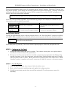
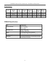
IPGSM-DP Trouble Detection Information
Telco 1 is used for the Fire Panel to output contact ID messages to the IPGSM-DP, and Telco 2 is used by the
IPGSM-DP to report faults to the Fire Panel. If Telco 1 is not operational, the Fire Panel will use Telco 2 to
report events if there are no faults in the iGSM Communications module.
Fault Condition Indication to Fire Panel
PowerBoost1 fault Telco 2 is cut.
iGSM Communications Module fault
Failure of one of the two
communications paths.
Telco 2 is cut.
Failure of both communications
paths.
Telco 1 and 2 are cut.
Dialer Capture Module buffer is full. Hang up. (Panel will retry, giving the buffer a chance to empty.)
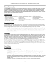
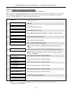
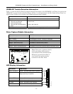
Dialer Capture Module Information
LED Indicator STATUS
RED – Steady ON Messages exist in buffer.
RED – Flashing No messages to be sent. Waiting for messages.
GREEN – Steady ON Normal Indication.
GREEN – Blinks every 2 sec. PowerBoost1 communication problem.
GREEN – Blinks twice every sec. Communication Module connection is lost.
GREEN – Blinks 10 times every sec. PowerBoost1 and Communications Module connection is lost.
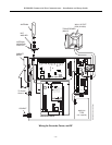
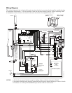
iPGSM-COM-004-V0
Dialer Capture Module
Telco 1
Telco 2
ECP
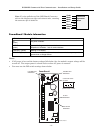
Tip 2
Ring 2
ZN-
EOL
EOL
ZN+
PWR
GND
Tip 1
Ring 1
Data Out
Data In
12V In
GND
RED
GREEN
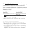
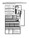
LED Display Information
Panel Status LED Indicator
RADIO TROUBLE Yellow – ON when radio trouble is present.
Buzzer – Upon loss of AC power, this will
beep once every 10 seconds.
LOW BATTERY Yellow – ON when battery is low.
Yellow – (not used)
AC LOSS Yellow – ON when no AC is present.
AC ON Green – ON when AC is present.
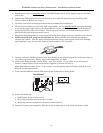
Note: Telco ports 1 (primary dialer)
and 2 (secondary dialer) may be
used instead of the terminal board.
Whichever connection method is
used, both Telco paths must be
connected to the Fire Panel.
iPGSM-COM-006-V0
Buzzer