


IPGSM-DP Commercial Fire Communicator – Installation and Setup Guide
– 9 –
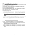
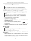
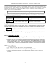
Note: If a wire pulled out of the LED Board Connector
refer to the diagram on right and reinsert wire, ensuring
the connector pin is locked in.
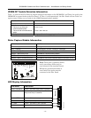
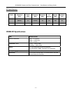
PowerBoost1 Module Information
LED Indicator STATUS
AC
(green)
AC power available.
ACTIVE
(green)
Cyclical flashing – normal communications.
Repetition of 3 flashes – loss of communications.
LOW BATT (yellow) Missing or low battery.
TROUBLE (yellow)
One or more trouble conditions exist, such as; overload, output supervision,
ground fault, or charger failure.
Notes:
If AC power is lost and the battery voltage falls below 10v, the module's output voltage will be
turned off. The output power is turned back on when AC power is restored.
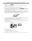
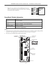
You must use the DIP switch settings shown below.
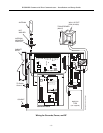
iPGSM-COM-003-V0
TROUBLE LED
INDICATOR
PowerBoost1
15
ON
2
3
4
Confiure DIP switch
as shown:
AC LED
INDICATOR
ACTIVE LED
INDICATOR
LOW BATT LED
INDICATOR
15
ON
2
3
4
(Switch handle = white)
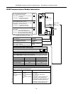
NC
NC
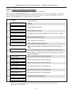
LED Board
Connector
Wires
Violet
Black
White
Red
Brown
Yellow
Gray