


T775A/B/M SERIES 2000 CONTROLLER 2. SETUP (ADVANCED OPTIONS)
62-0254–03 22
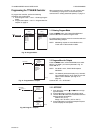
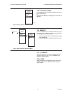
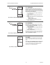
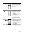
Fig. 47. Setup - Outputs - Mod Out - Type.
2.3.1.1. TYPE (of output signal)
1. From the Mod menu, use the S and T buttons to
highlight TYPE.
2. Press the X button to display the Type selections.
3. Use the Sand T buttons to highlight the desired
output type.
Default: 4-20 mA
4. Press the X button to accept the selected type and
return to the Mod menu.
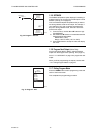
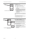
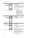
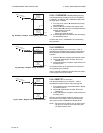
Fig. 48. Setup - Outputs - Mod Out - Minimum Output
Percentage.
2.3.1.2. MIN OUT %
The minimum output % prevents the output from dropping
below the value entered. This value can be useful to
maintain minimum damper position.
Using the time clock or digital input to disable the output
forces the output to 0%.
1. From the Mod menu, use the S and T buttons to
highlight MIN OUT %.
2. Press the X button to display the Min Out %.
3. Use the S and T buttons to increase/decrease the
desired value from 0% to 100% in 1% increments.
Default: 0%
Range: 0 to 100%
4. Press the X button to accept the percentage and
return to the Mod menu.
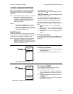
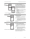
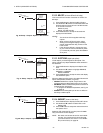
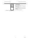
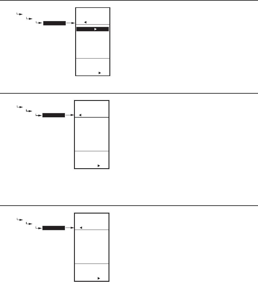
Fig. 49. Setup - Outputs - Mod Out - Integral.
2.3.1.3. INTEGRAL
1. From the Mod menu, use the S and T buttons to
highlight INTEGRAL.
2. Press the X button to display the Integral seconds.
3. Use the S and T buttons to increase/decrease the
value from 0 to 3,600 in 10 second increments.
Default: 400 seconds
Range: 0 to 3,600 seconds
4. Press the X button to accept the seconds and
return to the Mod menu.
NOTES:
1. The Integral time is factory set for 400 seconds. This
is a good middle range and should satisfy many
applications. The integral time can be increased for
applications where sensed response is slow, and can
be decreased for applications where sensed
response is fast (e.g. discharge air control).
2. As a starting point, an optimal integral time for
discharge air typically ranges from 12 to 200
seconds. An optimal integral time for room control
typically ranges from 60 to 2,500 seconds. The
purpose of integral action is to reduce or eliminate
the offset from setpoint during steady state control
that is often seen in proportional only control.
3. Keep in mind that control is most sensitive to
throttling range. Adjust the throttling range first
before any adjustment to integral time. Adjust
throttling range to be as wide as possible to start
since this will provide the most stable control.
Remember that the integral will eliminate the steady
state error so you do not need to have a small
throttling range to have accurate control. (Integral
action allows for controlling to a setpoint even with a
wide throttling range).
SETUP
OUTPUTS
MOD 1
TYPE
SETUP
OUTPUTS
MOD 1
TYPE
SELECT
TYPE FOR
MOD 1
4 - 20 mA
0-10 V
2-10 V
SERIES 90
M24513
SETUP
OUTPUTS
MOD 1
MIN OUT %
ENTER
MINIMUM
PERCENT FOR
MOD 1
SETUP
OUTPUTS
MOD 1
MIN OUT %
0
%
M24514
SETUP
OUTPUTS
MOD 1
INTEGRAL
ENTER
INTEGRAL
TIME FOR
MOD 1
SETUP
OUTPUTS
MOD 1
INTEGRAL
400
SEC
M24515