


WIRING T775A/B/M SERIES 2000 CONTROLLER
5 62-0254–03
Controller Wiring
WARNING
Electrical Shock Hazard.
Can cause severe injury, death or property
damage.
Disconnect power supply before beginning wiring,
or making wiring connections, to prevent electrical
shock or equipment damage.
CAUTION
Do not use 24 Vac power to power any external
loads if 120 Vac or 240 Vac is used to power
the T775A/B/M controller.
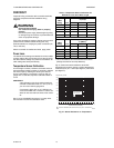
CAUTION
A separate earth ground is required.
Equipment damage can result if the earth ground
is not connected. See Fig. 5 and Table 2 on
page 6.
CAUTION
Equipment Damage Hazard.
Electrostatic discharge can short equipment
circuitry.
Ensure that you are properly grounded before
handling the unit.
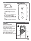
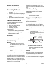
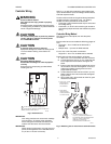
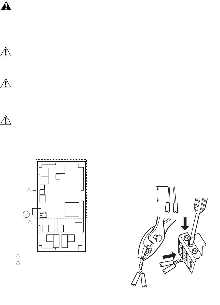
Fig. 5. Earth Ground.
IMPORTANT
Poor wiring practices can cause erratic readings
from the sensor. To ensure proper operation,
ensure that good mechanical connections are
made to both the sensor and the controller.
IMPORTANT
When wiring the input power, only one source of
power can be applied to the T775A/B/M control-
ler (24 Vac or 120 Vac or 240 Vac).
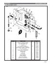
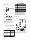
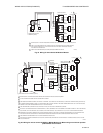
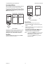
See Fig. 7 on page 6 for locating the appropriate power
input, remote sensors input, low voltage, contact closure,
and load output terminals.
Access to the terminals can be gained through standard
conduit knockouts (A through E in Fig. 7 on page 6)
located around the perimeter of the enclosure:
• Knockouts A and B should be used only for sensor and
low-voltage wiring.
• Knockouts C, D, and E can be used to gain access to
the load relay output terminals and 120/240 Vac power
wiring.
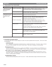
Controller Wiring Method
Wire the sensors and outputs, then wire the power
connection.
Each terminal can accommodate the following gauges of
wire:
• Single wire – from 14 AWG to 22 AWG solid or
stranded
• Multiple wires – up to two 22 AWG stranded
For 24, 120, or 240 Vac power connections:
Single wire – from 14 to 18 AWG solid or stranded
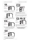
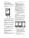
Prepare wiring for the terminal blocks, as follows:
1. Strip 1/2 in. (13 mm) insulation from the conductor.
2. Cut a single wire to 3/16 in. (5 mm). Insert the wire
in the required terminal location and tighten the
screw.
3. If two or more wires are being inserted into one ter-
minal location, twist the wires together a minimum
of three turns before inserting them to ensure
proper electrical contact.
4. Cut the twisted end of the wires to 3/16 in. (5 mm)
before inserting them into the terminal and tighten-
ing the screw.
5. Pull on each wire in all terminals to check for good
mechanical connection.
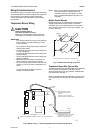
Fig. 6. Attaching two or more wires at terminal blocks.
C
+
W
1
2
M24296
NO HIGH VOLTAGE. CLASS 2 WIRING ONLY.
EARTH GROUND TERMINAL MUST BE CONNECTED
TO CONDUIT CLAMP LOCALLY.
1
2
1/2 (13)
1. STRIP 1/2 IN. (13 MM)
FROM WIRES TO
BE ATTACHED AT
ONE TERMINAL.
2. TWIST WIRES
TOGETHER WITH
PLIERS (A MINIMUM
OF THREE TURNS).
3. CUT TWISTED END OF WIRES
TO 3/16 IN. (5 MM) BEFORE INSERTING
INTO TERMINAL AND TIGHTENING SCREW.
THEN PULL ON EACH WIRE IN ALL
TERMINALS TO CHECK FOR
GOOD MECHANICAL CONNECTION.
M24473