


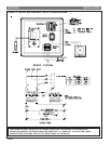
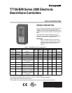
T775A/B/M SERIES 2000 CONTROLLER WIRING
62-0254–03 4
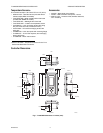
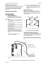
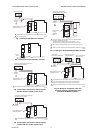
Wiring Connections Access
To access the wiring connections, remove the two screws
on the left side of the enclosure and gently swing open the
top. Be careful to not stress the ribbon cables that
connect the keypad and LCD display to the controller
circuit board.
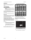
Temperature Sensor Wiring
CAUTION
Electrical Shock Hazard.
Can short equipment circuitry.
Make sure that metal tube of sensor does not
short against T terminals in wall-mounted case.
IMPORTANT
Poor wiring practices can cause erratic readings
from the sensor. Avoid the following to ensure
proper operation:
• Do not route the temperature sensor wiring with
building power wiring.
• Do not locate the temperature sensor wiring next
to control contactors.
• Do not locate the temperature sensor wiring near
electrical motors.
• Do not locate the temperature sensor wiring near
welding equipment.
• Make sure good mechanical connections are
made to both the sensor and the controller.
• Do not mount the sensor with the lead wire end
pointing up in an area where condensation can
occur.
If any of the above conditions cannot be
avoided, use shielded cable.
NOTE: Each T775 controller must be wired to its own
sensor(s). However, a benefit of the T775
controller’s accuracy is that there is no more
than a 2°F differential between any two T775
controllers.
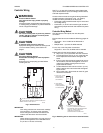
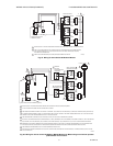
Multiple Parallel Sensors
Multiple sensors can be parallel-series wired to sense
average temperatures in large spaces. To maintain
control accuracy, the number of sensors to be parallel-
series wired must be of the n
2
power (for example, 4, 9,
16, etc.). See Fig. 3.
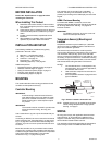
Fig. 3. Parallel-series wiring of sensors.
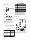
Temperature Sensor Wire Type and Size
Temperature sensors use standard AWG 18/2 unshielded
wire. For cable runs greater than 25 feet or where
electrical interference may be a problem, shielded cable
is recommended. See Fig. 4.
Refer to “Temperature Sensor Calibration” on page 10 for
wire size selection where cable runs are longer than 25
feet.
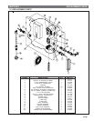
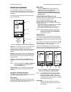
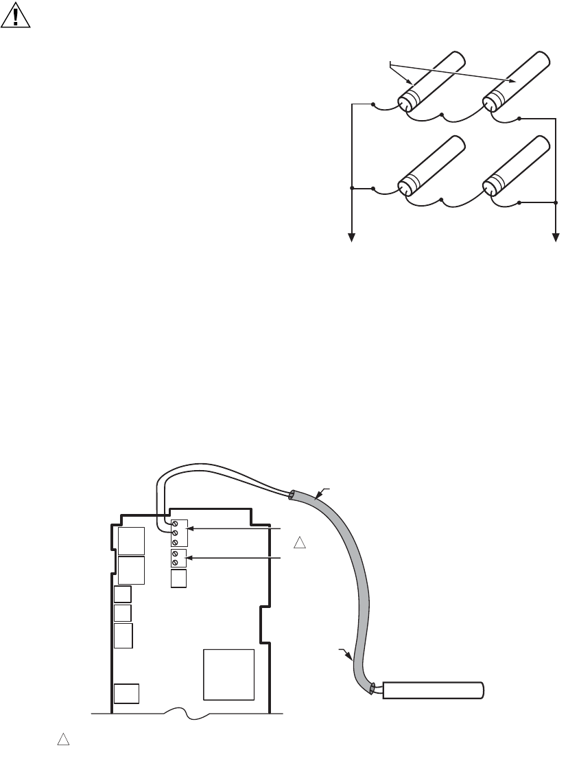
Fig. 4. Sensor wiring — showing shielded cable connection to Sensor A.
TO T775 CONNECTIONS (SENSOR A) OR (SENSOR B).
SENSORS
M24471
M24472
SHIELDED
CABLE
SHIELDED
CABLE
SENSOR
SENSOR A AND SENSOR B TERMINAL WIRING IS POLARITY INSENSITIVE.
1
NOTE: SHIELDED CABLE MUST BE
CONNECTED TO AN EARTH
GROUND.
HOWEVER, DO NOT GROUND
SHIELDED CABLE AT SENSOR END.
NOTE: TO MINIMIZE NOISE PICKUP,
MAKE SENSOR CONNECTION FROM
SHIELDED CABLE AS CLOSE AS
POSSIBLE TO SENSOR BODY.
T
T
T
T
SENSOR A
SENSOR B
1