


INTERFACE OVERVIEW T775A/B/M SERIES 2000 CONTROLLER
11 62-0254–03
INTERFACE OVERVIEW
The T775A/B/M controllers use an LCD panel and
6-button keypad to provide status information and permit
user input of the programming, setup, and scheduling
parameters.
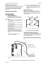
The following figure describes the display areas of the
LCD and the keypad.
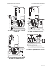
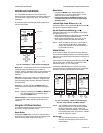
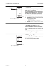
Fig. 22. LCD Display - Home Screen And Keypad.
Menu Area – On the home screen, the LCD displays the
configured relays and whether they are active. In
Program, Setup or Schedule mode, the LCD displays the
current menu selection and its order within the menu
hierarchy.
Data Area – On the home screen, the LCD displays the
sensors and outputs status. In Setup or Program mode,
the LCD displays menu choices, parameter selections,
and data values.
Lock Icon – The icon indicates the MENU button is
locked and prevents access to the Setup and Program
menus.
NOTE: Pressing and holding the HOME and MENU but-
tons simultaneously for five seconds locks/
unlocks the MENU button.
6-Button Keypad – The keypad is used to access the
menus and enter values (see “Using the LCD Panel
Interface”).
Using the LCD Panel Interface
The 6-button keypad is used to move through the menus
and enter or change parameter values.
Home Button
Pressing the HOME button at any time exits the current
Programming or Setup display screen and returns to the
home screen as shown in Fig. 22 and Fig. 23.
Menu Button
•Pressing the MENU button always displays the
Program menu. If you are in Setup mode, you exit
setup and return to the Program menu.
• Pressing and holding the MENU button for five
seconds leaves the current screen and displays
the Setup menu.
Left and Right Arrow Buttons (
W and X
)
Use these buttons to move backward (W) and forward (X)
through the Program and Setup menus.
Up and Down Arrow Buttons (
S and T
)
Use these buttons to move your selection up and down
through a menu or list.
• When the desired item is highlighted, you press the X
arrow button to display that item’s content.
• When a value is displayed (e.g. 70°F), the up and
down arrows increase and decrease the value.
NOTE: Once you select an item from a list or enter a
value, pressing the W or X or HOME button
accepts your selection or value and stores it in
the controller’s memory.
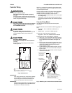
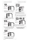
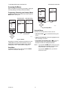
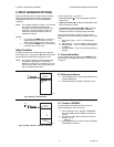
Home Screen
In the normal run state, the LCD home screen displays
the current sensed temperatures, the modulating outputs
status, the active status of the output relays, and error and
status codes.
Active relays are indicated by the small black square ()
just below the relay number. Fig. 23 shows the home
screen with relays 1, 2, and 4 energized.
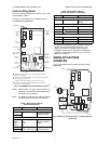
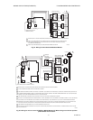
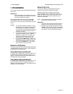
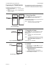
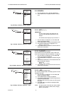
Pressing the W and X buttons from the home screen
cycles through each modulating output that is paired with
the sensor it controls and the active output relays.
Fig. 23. LCD Display - Home Screen Displaying
Sensors, Active Relays, and Mod Outputs.
NOTE: The modulating output home screen and the
relay home screen do not dynamically update
the active relay status, sensor values, and
modulating output percentages. The information
is a snapshot taken when you press the W or X
button to display the screen.
IMPORTANT
After four minutes of inactivity (no buttons
pressed), the LCD display reverts to the home
screen display.
MOD1 40%
MOD2 60%
DI ON
HOME
RELAYS 1 2 3 4
ON
SENSORS
SENSOR A
78
SENSOR B
84
MENU AREA
home menu
F
o
F
o
DATA AREA
LOCK ICON
6 BUTTON KEYPAD
M24488
MOD1 40%
MOD2 60%
DI ON
HOME
RELAYS 1 2 3 4
ON
SENSORS
SENSOR A
78
SENSOR B
84
o
o
F
F
MOD1 40%
MOD2 60%
DI ON
HOME
RELAYS 1 2 3 4
ON
o
F
o
F
REL 1 ON
HEAT
SETPOINT
60
SENSOR A
62
RT 12345 HRS
DI ON
HOME
RELAYS 1 2 3 4
ON
MOD 1 40%
COOL
SETPOINT
74
SENSOR A
62
o
o
F
F
M24489
MOD1 40%
MOD2 60%