


T775A/B/M SERIES 2000 CONTROLLER WIRING APPLICATIONS (EXAMPLES)
62-0254–03 6
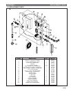
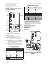
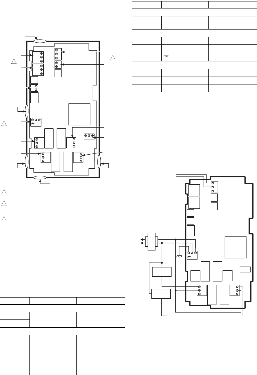
Controller Wiring Details
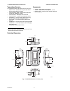
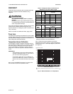
The wiring connection terminals are shown in Fig. 7 and
are described in Table 2.
See Fig. 8 – Fig. 20 beginning on page 6 for typical
T775A/B/M wiring applications.
Fig. 7. T775A/B/M terminal and feature locations.
NOTE: Refer to Table 1 on page 1 for the specific con-
figuration of sensors and outputs supported by
the model you are installing.
NOTE: For NEMA 4 enclosures, use waterproof fittings
for wiring/conduit connections at knockouts.
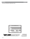
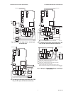
WIRING APPLICATIONS
(EXAMPLES)
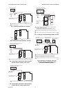
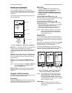
Fig. 8 – 20 illustrate typical controller wiring for various
applications.
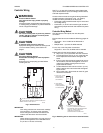
Fig. 8. Wiring for two-stage control – 24 Vac input and
24 Vac load.
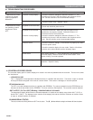
Table 2. Description of Wiring
Terminal Connections.
Connection Terminal Label Description
Sensors
Sensor A
T T
Temperature Sensor;
polarity insensitive
Sensor B
Outputs
Relay 1
Relay 2
Relay 3
Relay 4
NO
COM
NC
120-240 Vac Relay
Output
Mod 1
+ - (Vdc or mA)
W R B (Series 90)
a
Modulating Output
Mod 2
M24474
C
NO
NC
C
NO
NC
C
NC
NO
C
NC
NO
T
T
T
T
B
R
W
+
–
+
–
B
R
W
+
–
SENSOR A
SENSOR B
MOD 2
MOD 1
KNOCKOUT A
DIGITAL
INPUT
POWER
120/240 VAC
OUTPUT
RELAY 2
KNOCKOUT D
POWER
24 VAC
OUTPUT
RELAY 1
KNOCKOUT C
KNOCKOUT E
SENSORS A AND B USE THE TWO TT CONNECTIONS AND ARE
POLARITY INSENSITIVE.
FOR MOD 1 AND MOD 2 CURRENT (mA) OR VOLTAGE (VDC) OUTPUT,
USE SIGNAL (+) & COMMON (-).
FOR MOD 1 AND MOD 2 SERIES 90 OUTPUT, USE W, R, & B.
A SEPARATE EARTH GROUND IS REQUIRED FOR ANY POWER
SOURCE (24, 120, OR 240 VAC).
1
2
1
2
OUTPUT
RELAY 3
KNOCKOUT B
OUTPUT
RELAY 4
3
3
C
+
120
COM
240
Input
DI + - Digital Input (dry
contact)
24 Vac Power
24V + + 24 Vac Hot
Common C 24 Vac Common
Ground
Earth Ground
b
120 or 240 Vac Power
120 Vac 120 120 Vac Power
Common COM Common
240 Vac 240 240 Vac Power
a
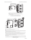
For Series 90 connections, you must insert a 340 Ohm
resistor across terminals R and W. See Fig. 17 on
page 8. The resistor is included with the controller.
b
A separate earth ground is required for all installations
regardless of the power source (24, 120, or 240 Vac).
See Fig. 5 on page 5.
Table 2. Description of Wiring
Terminal Connections. (Continued)
Connection Terminal Label Description
L1
(HOT)
L2
24 VAC
COM
NO
COM
NO
M24475A
LOAD 2
LOAD 1
SENSOR A
C
NO
NC
C
NO
NC
T
T
C
+