


M-511401 96d User Manual 13
8/10 Honeywell
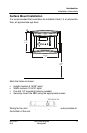
Introduction
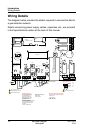
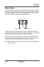
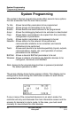
Wiring Details
The connectors, or ports, on the PCB allow various wiring to be
connected to the controller. The wiring includes power, communication,
BACNet and relays, each with an assigned position (and number) on
the board:
J22 Power Input: Connect the power supply to the controller
(see Wiring Details for cabling diagrams)
J23, J24 Communication
inputs: Connect communication cables to channels 1
through 3.
Relay Outputs 1-4: Depending on the desired configuration,
connect the relay cables to either N.O. or N.C.
SHDN jumper Place the jumper over the Shutdown header
pins to reset or restart the system.
EOL Resistors 1-4: Place the jumper over the header pins to
create the connection to attenuate
communication echoes.