12 96d User Manual M-511401
Honeywell 8/10
Introduction
Wiring Details
Wiring Details
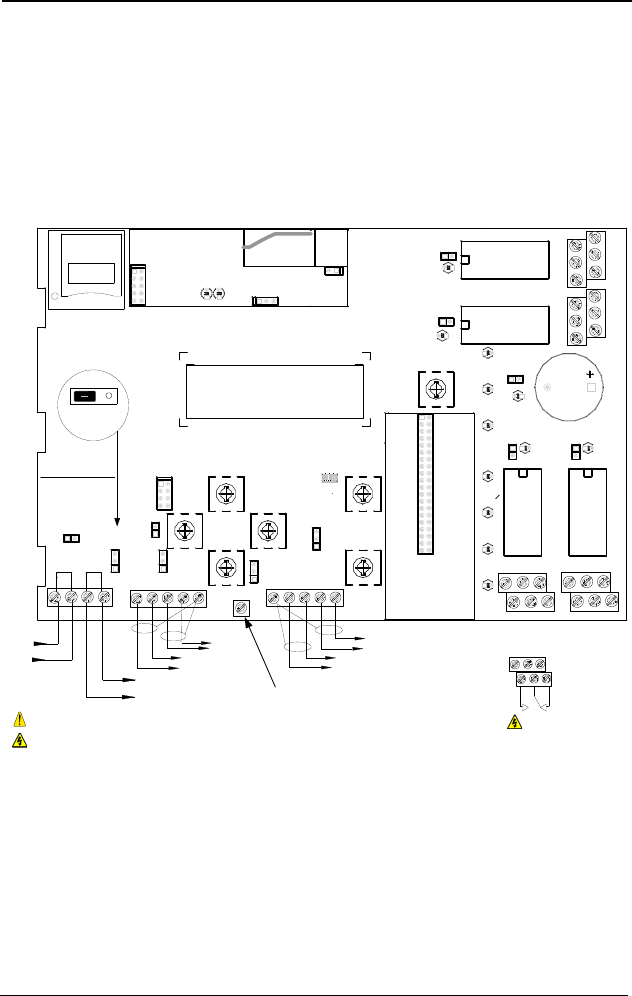
The diagram below provides the details required to connect the 96d to
a gas detection network.
Details concerning power supply, cables, capacities, etc., are provided
in the Specifications section at the back of this manual.
COMMUNICATION
Communication Wire Gauge:
2-24 AWG (Belden 9841)
Twisted and shielded cable
2000 feet (600 m) per channel
T-tap: 65 feet (20 m) / T-tap
130 feet (40 m) total
Channel Specifications:
Channel 1-2: Modbus,Vulbus protocol
Channel 3: Modbus protocol only
Communicates only with Vulcain
transmitters
Channel 4: Modbus output
Communicates only with VA301BDCM
Channel 4 (not used)
Channel 3
A 4
B 4
A 3
B 3
Channel 2
Channel 1
B 2
A 2
A 1
B 1
V-
NEXT
V+
PREVIOUS
V-
V+
5(6(7
3&%&:5$
6+,(/'
6+,(/'
6+'1
9
%$%$
%$
5,*+7
/()7
5;
7;
$/$50B$
%
$
9
$/$50B%
$/$50B&
32:(5
)$8/7
'2:1
(17(5
(6&
6,/(1&(
1&
12
12 1&
83
0$'(,1&$1$'$
5&
5&
5&
5&
5
5
5
5
5(/$<
5(/$<
5(/$<
5(/$<
9LQ 9RXW
(7+(51(702'8/(
99
-
-
-
-
-
5
/('
/('
/('
/('
/('
&
6:
6:
6:
6:
6:
6:
/('
/('
/('
/('
/('
/('
/('
.
-
-
-
(2/
(2/
(2/
(2/
%=
-
-
-
-
-
-
-
.
.
/
5
-
6:
-
.
0DGHLQ&DQDGD
9XOFDLQ,QF
9$&:35%
5(6(7
-
-
'
'
-3
/
1&
12
12
Ethernet: 10/100-compatible with 10Base-T
interface, RJ-45
Visual Indicators:
Green LED LINK
Yellow LED ACT
BacNet/IP MODULE (-BIP option)
Always respect minimum
voltage requirements at device
LCD screen
Wireless
communication module
Wireless Communication:
ISM worldwide
Indoor range 30m
RELAY OUTPUTS
3+5
4+6
1+3
2+4
Normally
open
Normally
closed
5
31
642
RISK OF ELECTRIC SHOCK
RISK OF ELECTRIC SHOCK
End-of-line specification:
The E.O.L. jumper for
channels 1-2-3-4 must
always be in E.O.L.
position.
End-of-line jumper
position
5&
5
SD Card
Grounding screw


