


HONEYWELL MODEL 700/800 SIGNAL PROCESSOR AND VIEWING HEAD
9 66-2069—02
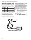
position has been decided. A continuous flow of air must be
maintained in order to reduce the conducted heat and to keep
the sight pipe and viewing head lens free of dirt and debris. Air
required is about 5 SCFM (0.13 Nm3 /min) delivered at 1 in.
(25mm) above the maximum pressure as measured at the “Y”
or “T” section of the purge air connection for each viewing
head. The air supply must be clean, free of oils and water, and
preferably cool. In order to electrically isolate the viewing
head, the purge air line should be installed using an insulating
material, such as a rubber hose, in between the purge air line
and the viewing head.
Vibration
Do not install the viewing head where it could be subject to
high vibration. Provide an anti-vibration mount if excessive
vibrations are present.
Clearance
Make sure there will be sufficient room to remove the viewing
head housing for servicing.
Viewing Head Mounting
Honeywell offers a range of swivel mounts, both pipe thread or
flange mounting for use with sight pipes or direct wind box
mounting. See “Accessories” on page 9 or the Honeywell
website for further details.
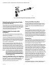
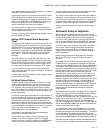
Viewing Head Sighting
The sighting of the viewing head should be parallel to the
center line of the burner in the direction of the flame. If used,
the sight pipe should be mounted as close to the center line
as possible so as to sight along the flame rather than across
the flame. Doing so will ensure continuous flame detection
under changing load conditions. See Fig. 15, 16 and 17.
Utilizing a sighting or the sight pipe aimed at the root of the
flame (where the turbulent combustion air mixes with the
flame) is a good starting point for optimizing the sighting.
Where practical, using a swivel mount to “zero-in” on the
highest signal will assure maximum performance. The
optimum scanner location is parallel to the burner center line.
The use of a swivel mount allows for line of sight adjustment,
where practical to use.
Examples of viewing head installation with and without a
swivel mount are shown in Fig. 13 and Fig. 14. If using a sight
pipe, its diameter should be large enough to allow a
reasonable field of view, and to allow for adjustment of the
swivel mount angle.
In some instances, it may be beneficial to use two sets of
setpoints for Flame On, Flame Off and gain. The two-channel
capability (primary and alternate viewing head settings) is
ONLY possible when using the P531 or P532 signal
processors; it is not possible when using the 700ACSP or
700DCSP signal processors. The switch-over from Channel A
to Channel B can be implemented from the burner control
system. Refer to the P531/P532 user manual, 66-2068, for
further information regarding switch-over and the use of
Channels A and B with independent settings.
ACCESSORIES
Orifice disks (kit M-702-6) - Used to reduce the signal
brightness in cases where the signal brightness is too strong.
Located immediately in front of the lens, it will reduce the
amount of signal to the sensor. Bag assembly contains orifice
disks and retaining rings. Orifice disks come with 3/8, 1/4,
3/16 and 1/8 inch diameter holes. Contact the factory for
guidance in using orifice disks.
Insulating nipple (R-518-13) - 1/2-in. NPTM Ultem heat and
electrical insulating nipple typically used in conjunction with a
swivel mount and union.
VH insulating mounting block (700UA, 800UA) - 1/2 in.
NPTF Ultem heat and electrical insulating mounting block,
used in place of the supplied Delrin mounting block. 1/4 in.
NPTF purge air connection. Typically used in conjunction with
a swivel mount. Rated for continuous service up to 320°F
(160°C).
Swivel mounts, small (700-1, 700-2, 700-3) - All have 1/2 in.
NPTM viewing head connections on one end with varying
process connections including 1 in. NPTF, 1/2 in. NPTF and
1/2 in. flanged.
Swivel mounts, large (M-701-1, M-701-2, M-701-2-FLG, M-
701-2-SS, M-701-3, M-701-3P, M-701-4) - All have 1 in NPTF
viewing head connections, one end with varying process
connections including 2 in. pipe slip on, 2 in. NPTF, 2 in.
flanged, 2 in. NPTF in stainless steel construction, 4.5 in.
flanged with 3 bolts, 3 in. NPTF and 2-bolt flanged.
Appropriate fittings must be used to adapt the 1/2 in. NPTF
viewing head process connections.
Insulating locking coupler adapters (R-518-PT13, R-518-
PT13L) - 1/2 in. NPTM Ultem adapters insulate the viewing
head electrically and thermally and are used with the R-518-
CL13-HTG locking couplers. The R-518-PT13L has a quartz
lens.
Locking coupler (R-518-CL13-HTG) - Used with the R-518-
PT13 and R-518-PT13L insulating locking coupler adapters.
Process connection end is 1/2 in. NPTF.
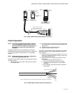
Connector - ASY786 --> Replacement field wireable
connector.
Cable and Connectors - S70X/S80X Viewing Heads
ASY785 --> 50 foot C330S cable with pre-wired ASY786
connector.
ASY785-200 --> 200 foot C330S cable with pre-wired ASY786
connector.
Cable (C330S) - 4-conductor with drain, foil/braided shield.
Sold per foot.
Isolation Units (ISO-UNIT, ISO-UNITSS, ISO-UNITHPGT) -
All have 1 in. NPTF connections with 1/2 in. NPTF purge ports
and quartz window. Painted aluminum or stainless steel
construction. The HPGT version has a 1/2 in. thick quartz
window for higher pressures. Appropriate fittings must be
used to adapt the 1/2 in. NPTF viewing head process
connections.
Air cooling canister (700ACC, 800ACC) - Has an air inlet
port on side. Used with vortex coolers. S80X models can be
used with the 700ACC if the 800ACC-RING adapter is used.