


HONEYWELL MODEL 700/800 SIGNAL PROCESSOR AND VIEWING HEAD
66-2069—02 10
Vortex coolers (M3204, M3208, M3210, M4025) - Used with
air cooling canister. Contact your distributor or the factory for
selection assistance.
Cable restraints (800CR, 700CRLT) - Liquid tight S80X and
S70X cable restraint versions. The 800CR includes the
700CRLT and the 800ACC-RING adapter.
S80X adapter ring (800ACC-RING) - Adapter ring to fit S80X
viewing heads to 700ACC cooling jacket and 700CRLT liquid
tight cable restraint.
Right angle adapter (700RAA) - S70X/S80X viewing head
right angle adapter. 1/2 in. NPTF to 1/2 in. NPTM connections.
Mounting blocks (700DA, 700DA-1, 800DA) - Delrin
replacement adapter/mounting blocks for S70X and S80X
viewing heads. All have 1/4 in. NPTF purge air connections.
Rated for continuous service up to 180F (82C). The 700DA
and 800DA have 1/2 in. NPTF process connections while the
700DA-1 has a 1 in. NPTF process connection. For more 1 in.
NPT accessories that can be used with the 700DA-1, refer to
the S55XB/BE manual, 66-2064.
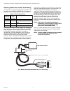
USB to RS422/RS485 Converter (COMMOD) - Protocol
converter for use with external communication with a remote
computer.
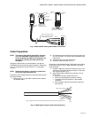
Fiber Optic System Compatibility - The S70X and S80X
viewing heads are compatible with the Honeywell FASA fiber
optic extension products. The S700FOAD and S800FOAD
adapters are applicable, depending on the application.
Contact your distributor or the factory for assistance with fiber
optic selection and pricing.
OPERATION
IR Detector
The S702 and S802 viewing head models use a Germanium
photodiode, which responds to IR radiation/flicker in the flame.
Flame flicker is caused by the combustion, or forced air
injected in to the flame. Combustion air can be mixed with the
fuel (pulverized coal) or can be introduced separately. In either
case, forced air is introduced in such a way as to aid the
combustion process. This air is usually made turbulent by
causing it to swirl with spin vanes located in the burner throat.
Flame flicker is created when turbulent air mixes with the
flame. It is composed of random frequencies and the amount
of high frequency flicker is dependent on the fuel and the
burner.
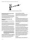
The S702, S702PF and S802 viewing head models respond
to flicker frequencies above 33Hz while the S702HF,
S702HFPF and S802HF viewing heads respond to flicker
frequencies above 155Hz. All flicker frequencies below the
filters are ignored, so it is important to sight the viewing head
on the highly turbulent portion of the flame that contains the
higher frequencies. The location of the higher frequencies can
be predicted by examining the burner with regard to where the
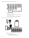
turbulent air enters the flame. The optimum scanner location
is parallel to the burner center line (Fig. 15). The use of a
swivel mount is encouraged to allow for line of sight.
Filter Selection for IR Viewing Head
If a good count ratio between BNR-ON and BNR-OFF cannot
be obtained when using an IR viewing head—particularly
when monitoring oil flames—an IR viewing head with the High
Frequency (HF) filter option is recommended. The standard IR
viewing head responds to flicker frequencies above 33 Hz;
with the HF option, the IR viewing head responds to flicker
frequencies above155 Hz.
UV Detector
The S706, S706PF and S806 viewing head models use the
UVTron tube, with a spectral response of 185-260nm and
peak response of 210nm to ultraviolet radiation. The output of
the detector is a pulse stream of randomly spaced pulses
whose average rate is proportional to the UV radiation present
in the flame. The UV radiation is a direct result of the
combustion process as oxygen combines with hydrocarbons
in the fuel in the blue part of the flame. The yellow part of
flames, and the background radiation from hot refractory, do
not emit UV radiation.
The spectral range of the UV tube makes it ideal for
discriminating between flame and glowing refractory. As with
any UV radiation, it can be absorbed or masked by unburned
fuel, smoke, oil mist, dirt dust and other impurities in the fuel.
Care should be taken to select the proper viewing head for the
fuel used. Additionally, the contaminants that mask UV can be
diluted by providing a strong flow of air through the sight pipe
to clear a viewing path through the attenuating material. See
“Purge Air” on page 8.
It may also be desirable to sight the detector at an area
containing fewer masking agents such as near the burner
nozzle or near the entrance of the combustion air. Increasing
the viewing area of the detector by shortening the sight pipe or
by increasing the diameter of the sight pipe can also reduce
the attenuating effects of the masking agents.
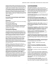
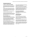
In general, the UV viewing heads will work well on natural gas
and light oil flames. The sighting for both oil and gas flames
should be parallel to the axis of the burner and aimed at the
root of the flame, as with the IR detector. (See previous
section, “IR Detector.”) The highest UV intensity occurs near
the root of the flame (Fig. 16). In addition, the zone of higher
UV intensity does not overlap the same zones of adjacent or
opposing burner so that, with proper sighting, discrimination
can be achieved.
With low NOx gas burners, the UV radiation is usually much
less in intensity and spread out. Relatively high readings can
be obtained from all over the furnace when many burners are
in service. This is particularly true when flue gas recirculation
is used. There will however, be a relatively stronger signal
near the “root” of the flame and the more intense spot should
be located during the aiming or sighting process. This “root” or
intense spot may be further out than with the standard gas
burner so it is imperative that a swivel mount be used when
making sighting adjustments.
Another factor that needs to be considered when aiming the
viewing head is the load condition of the boiler. The flames
from a burner can be radically different at different loads. This
is one of the reasons for choosing an optimum sighting initially
that will minimize signal swing due to changing loads.