


HONEYWELL MODEL 700/800 SIGNAL PROCESSOR AND VIEWING HEAD
15 66-2069—02
using key sequence below at the front panel of the
700 as follows:
1. Press and hold BNR-OFF SEQ START/END
button for 2 seconds.
2. Press up arrow to change setting from P0 to P1.
3. Press STORE.
The factory default Modbus address of the 700ACSP and
700DCSP is 0 and must be changed to a number between 1
and 32 to establish communication between the signal
processor and the host control. When more than one signal
processor is in the network, ensure that each signal processor
has a unique Modbus address within the range of 1 to 32.
Modbus RTU Function Supported
Four Modbus functions are supported:
• 01 Output coil read
• 03 Holding register read
• 06 Preset single holding register
• 16 Preset multiple holding register
NOTES:
— Before Model 700 signal processors are
connected to the RS-422 bus, their individual
Modbus addresses must be set to differing values
between 1 and 32.
— The RESET button on front of the 700ACSP or
700DCSP signal processors is used to set the
Modbus address.
— Press and hold the RESET button for two
seconds and the current address will appear. It
may be changed with the up or down arrow keys.
— Pressing the STORE button will store the new
address.
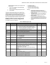
Table 4. MODBUS registers map.
Register Name Description Minimum Maximum
40001 FLAMECOUNT Flame count of active viewing head (read only) 0 3425
40002 PROCSTATUS Processor status bitmask (read only)
bit 1: flame on relay status (1=relay energized, 0=off)
bit 2: Processor Lockout status (0 =lockout, 1=not lockout)
bit 3: Panel access disabled (1=disabled, 0=enabled)
bit 4: 4 - 20 ma output (0=0 to 20, 1=4 to 20)
0255
40003 FLAMEON Flame On setpoint (read/write) 3 (S70X) 29
40007 OUTPUTGAIN Gain of the 0/4-20mA output (read/write) 20 80
40010 IRGAIN IR sensor gain setting (read/write) 1 9
40012 UVTGAIN UV tube gain setting (read/write) 1 9
40017 TYPE Viewing head type bitmask (read only)
bit 0: UV viewing head
bit 1: IR viewing head
--
40021 TIMEDELAY Time Delay (read only)
=1 for 700XXSP
12
40022 FFRT Flame failure response time setting in seconds (read/write) 1 3
40023 VERSION Firmware version (read only) - -
40024 MODEL Model number (read only) - -
40084 ERRORCODE Error code (read/write)
NOTE: writing a non zero number to this register is not allowed
--
40085 BAUD Baud rate setting (bits/second). Only affects RS-485
communication, not IRDA. (read, write)
96=9600 (default), 192=19200.
The SP and the master device must have the same baud
settings.
96 192
40086 PARITY Parity setting. Only affects RS-485 communication, not IRDA.
(read/write)
0= none (default), 1=odd
01
40087 ADDRESS Modbus address used by RS-485 and IRDA (read/write).
Each device must have a unique address.
0247
40089 PROTOCOL Protocol (read/write)
0=Honeywell protocol, 1=Modbus protocol
01