


HONEYWELL MODEL 700/800 SIGNAL PROCESSOR AND VIEWING HEAD
66-2069—02 6
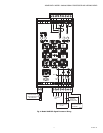
Viewing Head Connector and Wiring
Viewing heads are wired to the appropriate terminals located
on bottom of the 700ACSP, 700DCSP, P531 or P532 signal
processors. The terminals are listed functionally in Table 2.
Connectors and cables are shown in Fig. 3, Fig. 4, and Fig. 5.
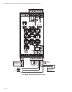
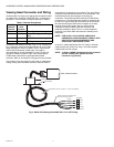
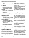
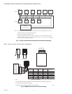
Fig. 3 shows the viewing head cable with the 1/2 in. NPT pipe
fitting and pigtail for use in a conduit. The PF model comes
with 50 feet of Honeywell C330S cable. This cable is
recommended for all new installations. It has ITC and CIC
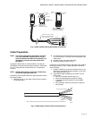
ratings for hazardous location. Figs. 4 and 5 describe the
C330S cable used with the right angle field-wireable
connector. Refer to “Accessories” on page 9 for part numbers.
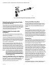
The customer may also supply his own cable; a replacement
mating viewing head connector should be ordered. Refer to
“Accessories” on page 9 for part numbers. The use of 22g, 4-
conductor cable with shield and drain is recommended. The
shield should be foil and braid type surrounding all
conductors. The shield should be connected to GND at the
processor end. The cable diameter should not exceed 0.307"
in order for it to go through the hex bushing in the connector.
But note that wiring the cable to the connector is not easy
because of the limited space. Also, the LED indicator
assembly must be mounted inside the connector and,
preferably, soldered in place. Thus, it is recommended to
purchase a pre-wired cable and connector assembly from
Honeywell.
NOTE: FOR CLASS I, DIV 2 RATING, CABLING IN
HAZARDOUS LOCATIONS MUST COMPLY WITH
NEC ARTICLE 500 REQUIREMENTS AND
APPLICABLE GOVERNING CODES.
In the U.S., cables should have UL’s ITC rating; in Canada,
cables should have CSA’s CIC rating. The recommended
C330S cable has both ratings.
NOTE: To obtain a NEMA 4X seal between the connector
and the viewing head, tighten the metal
connector ring securely.
Fig. 3. Model 700 Viewing Head Cable With 1/2 in. NPT Fitting.
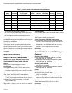
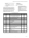
Table 2. Terminal Descriptions.
700ACSP or
700DCSP
Terminal
P531 or
P532
Terminal
Description
VH SIG VH3 SIG Flame Signal from Viewing Head
VH SC VH3 SC Shutter Drive Signal to Viewing
Head
VH +V VH3 +V +24VDC Power to Viewing Head
VH GND VH3 GND GND Signal Ground
WHITE
BLACK
RED
GREEN
TERMINAL
VH SIG
VH SC
VH +V
VH GND
CONDUIT
ENCLOSURE
S702PF, S702HFPF OR S706PF
SHIELD
C330S YELLOW 4-CONDUCTOR
WITH DRAIN AND SHIELD
STANDARD "PIGTAIL" LENGTH = 10 FEET (3 METERS)
M34285B