


HONEYWELL MODEL 700/800 SIGNAL PROCESSOR AND VIEWING HEAD
3 66-2069—02
APPROVALS
S70X/S80X Viewing Heads (Connector series and Pipe fit
series [PF])
CSA for CLASS I, DIV 2, GROUPS A, B, C, D & T4A
FM 7610/NEMA 4X and CLASS 1, DIV 2, GROUPS A, B, C, D
& T4A*
SIL 3 “Fit for Use”
IECEx CSA 10.0003 Ex nA IIC T4 Gc
-40<Ta<85ºC, -40<TA<185ºF
*IP67/NEMA 4/4X rating applies when connector ring is
properly tightened and cable is UV shielded
700ACSP and 700DCSP Signal Processors
CSA (C, US)
FM
INSTALLATION
When Installing These Products...
1. Read these instructions carefully. Failure to follow them
could damage the products or cause a hazardous
condition.
2. Check the ratings given in the instructions and one the
products to make sure the products are suitable for your
application.
3. Installer must be a trained, experienced, flame
safeguard control technician.
4. After installation is complete, check out product
operation as provided in these instructions.
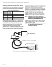
Signal Processor Mounting
The 700ACSP and 700DCSP signal processors mount on a
standard 35mm DIN rail. They snap into place and may be
released from the rail using a flat screwdriver.
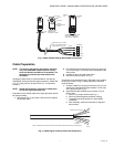
Grounding and Shielding
NOTE: Installer must be a trained, experienced flame
safeguard service technician and should be
familiar with the equipment operation and
limitations and be aware of any applicable local
codes and regulations.
1. Connect a safety ground to the viewing head housing (if
applicable). A ground screw is provided on the exterior
of the viewing head housing for this purpose.
WARNING
The viewing head housing is grounded through
cable/signal processor, so you must ensure that
AC/DC potentials at ground of signal processor
and viewing head are the same, or damage to the
cable or signal processor can result.
2. The viewing head and all associated cable/conduit must
be at least 12 inches (31 cm) from any source of high
energy or voltage (for example, igniter equipment).
3. Install a ground wire from the ignition transformer case
to the igniter assembly.
4. Ensure all igniter wires and cables show no signs of
wear. Replace any igniter cables or wires that are frayed
or cracked.
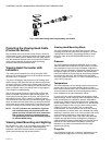
5. The viewing head must be electrically isolated from the
burner front.
a. Electrical isolation can be accomplished by
installing an Ultem nipple (R-518-13) or an Ultem
locking coupler adapter (R-518-PT13 or R-518-
PT13L) in conjunction with a locking coupler (R-518-
CL13-HTG) between the viewing head flange and
the burner mount.
b. The purge air line should also be isolated from the
viewing head. This can be accomplished by
installing any insulating material, for example a
rubber hose, in between the purge air line and the
viewing head.
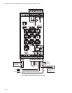
Signal Processor Power
Connections
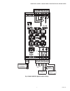
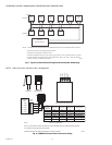
The Model 700ACSP power and relay connections are shown
in Fig. 1. The AC power supply to the 700ACSP Signal
Processor passes through a 2A fuse and an inrush current
limiter.
The Model 700DCSP power and relay connections are shown
in Fig. 2. The maximum current requirement for each
700DCSP is 250mA.
In the Model 700 signal processors the flame relay (RF A/B
ON, OFF, COM) has two sets of FORM C (SPDT) contacts
and the self-check relay (SC ON, OFF, COM) has one set (Fig.
1 and Fig. 2). The self-check relay is energized whenever the
signal processor is powered and is operating normally,
whether the flame relay is energized or not. Internally, the
flame relay is wired in series with the self-check relay (not
shown), which prevents the flame relay from energizing if the
self-check relay is not energized.
Unique fail-safe circuitry for the self-check and flame relays
ensure that in the event of any critical component failure
occurrence, system response will be to de-energize the self-
check relay, which in turn de-energizes the flame relay.
Some of the internal power wiring of the Model 700ACSP and
Model 700DCSP signal processors is shown in Fig. 1 and
Fig. 2. Rectifier diodes separate the battery backup input from
the main power bus until the battery voltage exceeds the
internal DC voltage plus a diode voltage drop. Resettable
fuses (shown as resistors with slashes) and conventional
fuses prevent internal failures from loading the power sources.
With the Model 700DCSP, if a backup battery is to be used
with a main power supply, the two power sources would be
wired as shown in Fig. 2. If no backup battery is to be
installed, the main power supply can be connected at +26V
PWR and GND as shown in Fig. 2 or it can be connected to
the +24V BATT input and GND. It is preferable to use the
battery connections because it takes advantage of the
resettable fuse at the battery input; resettable fuses recover
automatically from a fault within a few seconds after power is
removed. At the +26V PWR input and its associated GND,
conventional1A fuses are used because they are able to
protect against 240VAC being applied by accident (this could
happen if a Model 700DCSP is installed in a cabinet wired for
a Model 700ACSP).