


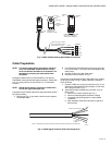
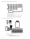
HONEYWELL MODEL 700/800 SIGNAL PROCESSOR AND VIEWING HEAD
11 66-2069—02
Self-Checking
The self-check circuitry guards against internal component
failure. There are several tasks that require intelligent
interaction between the viewing heads and the signal
processor. If all of these interactions do not occur properly, the
viewing head will not send pulses back to the signal processor
and the flame relay will open.
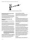
Adjustment of VH Sighting and Gain
NOTE: Adjustment to the viewing head parameters
cannot be made unless the viewing head is
connected and communicating with the signal
processor.
The viewing head should be properly sighted before the
setpoints are adjusted. Adjustment can be made easier by a
1/2 in. swivel joint, which Honeywell can supply if one is not
available (refer to “Accessories” on page 9).
While the burner is firing, vary the viewing angle while
observing the green LED on the connector at the rear of the
viewing head. Adjust the viewing angle for the maximum pulse
rate, then lock the swivel joint to preserve this mechanical
setting. If the green LED pulse rate is very high or very low,
see the two paragraphs below. The locked mechanical setting
should still be correct when Model 700 viewing heads are
interchanged, because inside each Model 700 viewing head
the optical axis is aligned with the mechanical axis within ±1/4
degree. Also, the reading shouldn’t change when a viewing
head is rotated in the mount.
For the above sighting adjustments to work properly, the
flashing rate of the green LED in the connector at the rear of
the viewing head must be reasonable. On the -PF (pipe fitting)
version, there are no LEDs. The installer must observe the
flame signal on the signal processor instead.
A count rate of 16 to 20 is recommended for proper operation.
If the displayed count is above 25, the pulses begin to blur
together, making changes in the pulse rate difficult to observe.
If the displayed count is less than 8 or 10, it will be difficult to
maximize the count by adjusting the viewing head aim, since
the pulses occur too infrequently. In such a case the gain
should be increased. If the gain is set to a maximum and the
count rate persists below 8 or 10, the system can still be made
to work reliably as long as the count rate drops significantly
when the flame is removed. However, the setup should be
reviewed for proper viewing head aim and sight path to ensure
it is optimized.
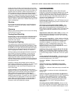
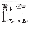
Orificing
Orifice disks have been used in applications with older viewing
heads that did not have adjustable gain in order to reduce the
extreme brightness of certain burner flames. The orifice disk
kit is part number M-702-6. Orifice disks come with 3/8, 1/4, 3/
16 and 1/8 inch diameter holes. Contact the factory for
guidance is using orifice disks. The disks are installed with
retaining rings in the flange at the edge of the 1/2 inch NPT
female pipe thread for the process connection. An internal
type retaining ring is first installed by positioning a ring in the
machined groove inside the flange opening from the housing
side. The orifice disk is then inserted. Use a second retaining
ring to hold it in place so that it is sandwiched tightly between
the two retaining rings.
If the displayed flame count is 25 or higher when the gain is
set to 1, an orificing disc inserted in the back end of the
mounting block can be used. Choose a disc that gives a
reading of 12 to 24 at a low fire firing rate. The discs have a
range of orifice sizes; each size step results in about a 2:1
change in the counts displayed.
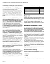
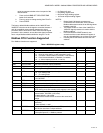
Signal Processor User Interface
The 700ACSP and 700DCSP signal processors have a user
interface that includes four lights, a two-digit display and
twelve push buttons for operation and programming. Each
button has at least one specific purpose.
To enter a menu, press and hold the applicable button for 2
seconds. Adjustments to the applicable setpoint can be made
via the INCREASE or DECREASE arrow buttons. To store the
new setting, press the STORE button until “--” is shown,
indicating the value has been accepted.
If no activity occurs for a period of four seconds while the
menu value is displayed, it will revert back to the operating
display.
To exit a menu at any time without saving changes, simply
press the RESET/rE button.
The following describes the functions of the LED indicators,
display and push buttons:
Front Panel LED Indicators and Display
• ON SEQ/AUTO SET LED (green):
— Used in conjunction with the BNR-ON SEQ START/
END and BNR-OFF SEQ START/END buttons during
the automatic setup process
• OFF SEQ/FAULT LED (green):
— Used in conjunction with the BNR-ON SEQ START/
END and BNR-OFF SEQ START/END buttons during
the automatic setup process
— Indicates a fault condition
• Two digit display
— When in operating mode, the display indicates the
current flame signal, which ranges between 00 and 29
— Upon power up, indicates whether an IR or UV viewing
head is attached and the selected gain setting; such
as r7 (IR with gain of 7) or u5 (UV with gain of 5).
— Indicates various characters during the automatic
setup process as well as whether the panel is locked
• FLAME SIG LED (yellow):
— When a flame is present, LED flashes at a rate
proportional to flame signal, except when the pulses
are interrupted once per second for viewing head self-
checks.
• FLAME ON LED (red):
— When the flame signal is above the selected value, the
LED will be illuminated and the flame relay will be
energized.
Push Button Functions
• RELAY ON SETPOINT button:
— Allows user to select flame on threshold value. When
the flame signal is above the selected value, the flame
relay will be energized. Used in conjunction with the