


HONEYWELL MODEL 700/800 SIGNAL PROCESSOR AND VIEWING HEAD
37 66-2069—02
Safety Function of the S702, S706,
S802, and S806
The S702, S706, S802, and S806 viewing heads do not have
a safety function. They are used to provide flame intensity
information via cables to Signal Processor Models 531AC,
531DC, 532AC, 532DC, 700AC, 700DC, and 800 which use
Flame Relays to provide a safety function.
S70X and S80X Viewing Head Proof
Test Interval
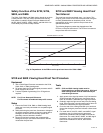
The proof test must be conducted every 1 to 5 years. This
range is given to allow for the test to be performed during the
normally scheduled burner shutdown period. It is the
responsibility of the user to perform the proof test in the
specified time frame.
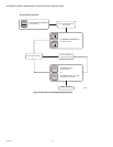
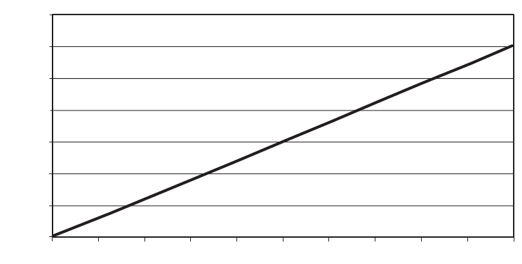
The following diagrams present the dependence of the
PFD
AVG
on the proof test interval. The PFD
AVG
increases as
the proof test interval increases.
Fig. 29. Dependence of the PFD
AVG
on the proof test interval for S706 & S806.
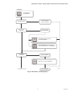
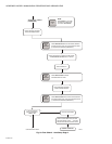
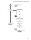
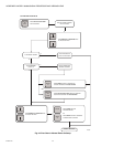
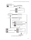
S70X and S80X Viewing Head Proof Test Procedure
Equipment
1. 700 or P532 Signal Processor connected to the S702,
S706, S802, or S806 viewing head.
2. DC power supply for DC model signal processor and AC
power supply for AC model.
3. A source capable of generating UV or IR signals as
required.
NOTE: For UV use Honeywell UVsource.
For IR connect incandescent lamp to AC source.
Setup
1. Ensure the S702, S706, S802, or S806 viewing head
under test is correctly connected to a compatible signal
processor.
2. While performing the proof test, disconnect or disregard
the signal processor outputs so that any outputs due to
testing do not affect the overall safety system and
potentially cause a hazardous situation.
3. Record all previously entered user programmable
settings so that you can restore them to their desired
values after the proof test.
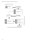
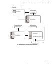
Tests
NOTE: S702 and S802 viewing heads must be
illuminated by an infrared light source. S706 and
S806 viewing heads must be illuminated by an
ultraviolet light source.
1. Apply power to the signal processor, fully illuminate the
viewing head with the light source, and ensure that a
flame on condition is indicated by the signal processor.
2. Gradually angle the light source away from the viewing
head. Ensure that the count decreases until a flame off
condition is indicated by the signal processor.
3. Cover the end of the viewing head with your hand and
ensure that the signal processor indicates a flame count
of zero.
4. For model 531AC, 531DC, 532AC, and 532DC, signal
processors, use your light source to generate a
flamecount of between 1200 and 2800, and note the
flamecount. For model 700AC, 700DC, and 800 signal
processors, use your light source to generate a
flamecount of between 12 and 22, and note the
flamecount.
0.00E
+00
5.00E
-06
1.00E
-05
1.50E
-05
2.00E
-05
2.50E
-05
3.00E
-05
3.50E
-05
0 1 2
3
4
5 6
7
8
9 10
TIME (YEARS)
PFD
AVG
M35040
S706 AND S806 PFD
AVG
VS TIME