


EXCEL 500/600 INSTALLATION INSTRUCTIONS
Setting the Module Address (not XCL5010)
In the case of application prior to CARE 4.0, you can set the
module address using the rotary HEX switches located on the
upper surface of the respective input and output modules.
The rotary HEX switch of Distributed I/O modules is situated
within the housing. The XP502 power supply module and the
XC5010C / XC6010 computer modules do not need a
hardware address.
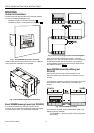
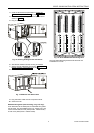
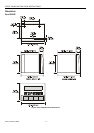
Fig. 8. Internal module HEX switch location
The 16 I/O modules (max. including Distributed I/O) are
addressed by means of the rotary HEX switch settings 0 to F.
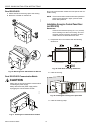
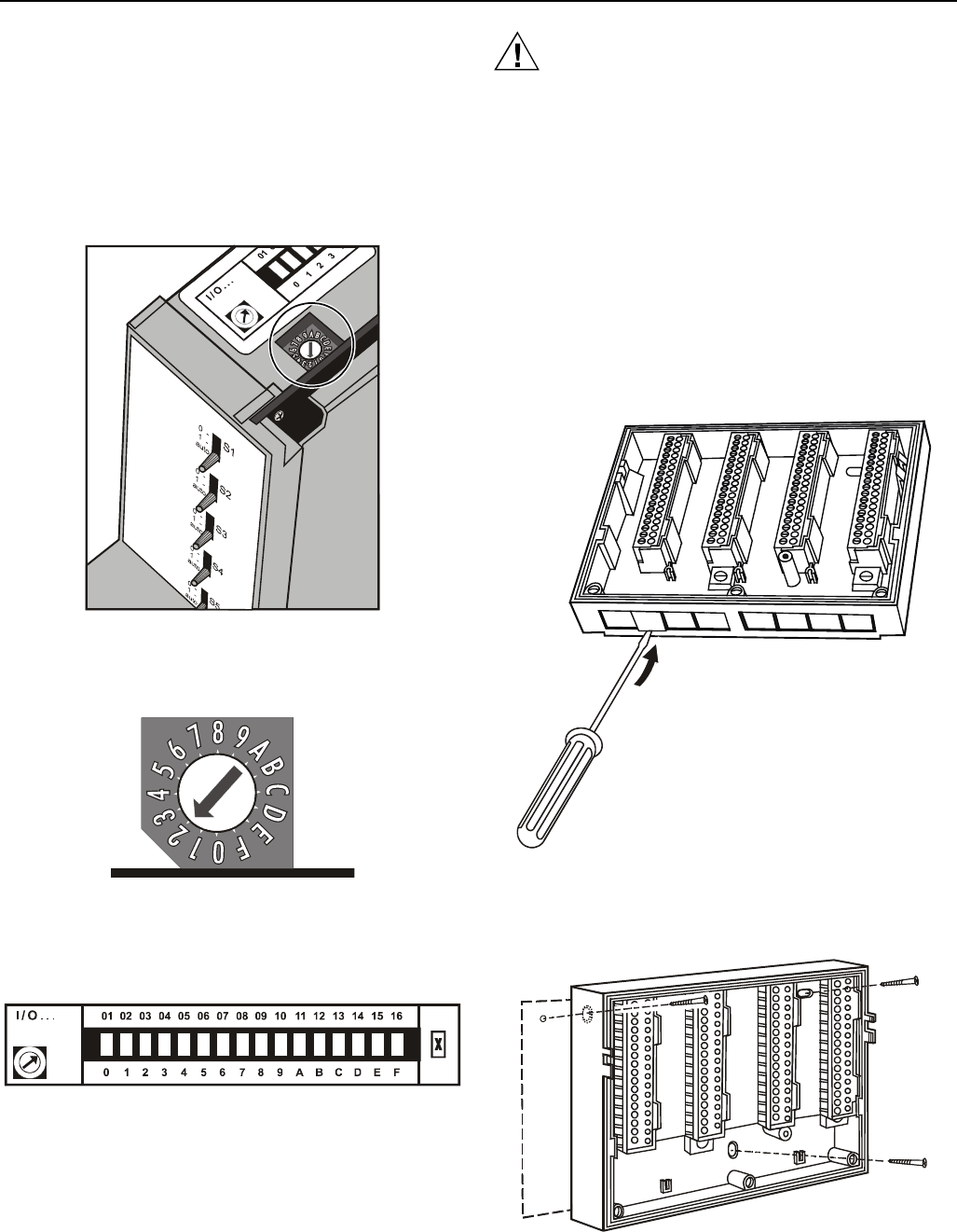
Fig. 9. Close-up of HEX addressing switch
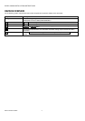
The relationship between the rotary HEX switch and the
module address can be seen on the label located next to the
rotary HEX switch.
Fig. 10. HEX switch label
Care should be taken to ensure that each module gets its
own module address. Addressing the modules in ascending
order 0 through F is recommended for the sake of clarity for
maintenance personnel.
CAUTION
Unplugging a module before switching OFF the power
supply could destroy the module. Do not unplug
modules with the power still connected. First switch
S1 on the power supply module to the 0 position.
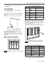
Installation Inside a Control Panel
Excel 500/600
IMPORTANT
Observe the minimum spacing of 1.5 in. (35 mm)
when installing more than one housing. Do not ex-
ceed the maximum spacing; otherwise, the tailor-
made internal bus cables will be too short.
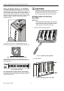
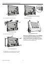
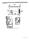
1. Break off cable entry strip segments.
Fig. 11. Cable entry strip segments
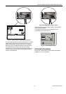
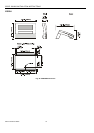
2. Install the base.
Fig. 12. Installing the base in the panel
EN1R-1047GE51 R0902 8