


EXCEL 500/600 INSTALLATION INSTRUCTIONS
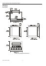
— Type XW569 13 in. (330 mm) long (for housings one
above the other)
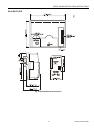
CAUTION
Incorrectly inserted bus cables can destroy the
modules installed.
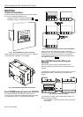
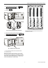
The internal bus begins at the first housing, containing the
power supply and computer modules, and ends at the last
housing.
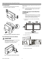
The protective bus connection covers must be removed.
Fig. 5. Removal of bus connection cover
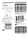
The overall internal bus length (bus cable and bus in the
housings) must not exceed 6 ft (2m).
Bus cables must be routed at least 2 in. (50 mm) away from
power cables to prevent possible inductive and capacitive
interference.
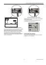
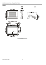
Module Locations (not XCL5010)
Each housing has four plug-in module locations.
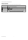
Table 1. Internal module locations
Module Type Module location
CPU
XC5010C /
XC6010
1
st
housing, location 4
Power
supply
XP502 1
st
housing, location 1
AI XF521A / XF526 any
AO XF522A / XF527 any
DI XF523A any
DO XF524A / XF529 not in the 1
st
housing
3-position
output
XF525A
not in the 1
st
module
housing
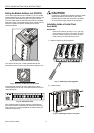
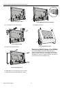
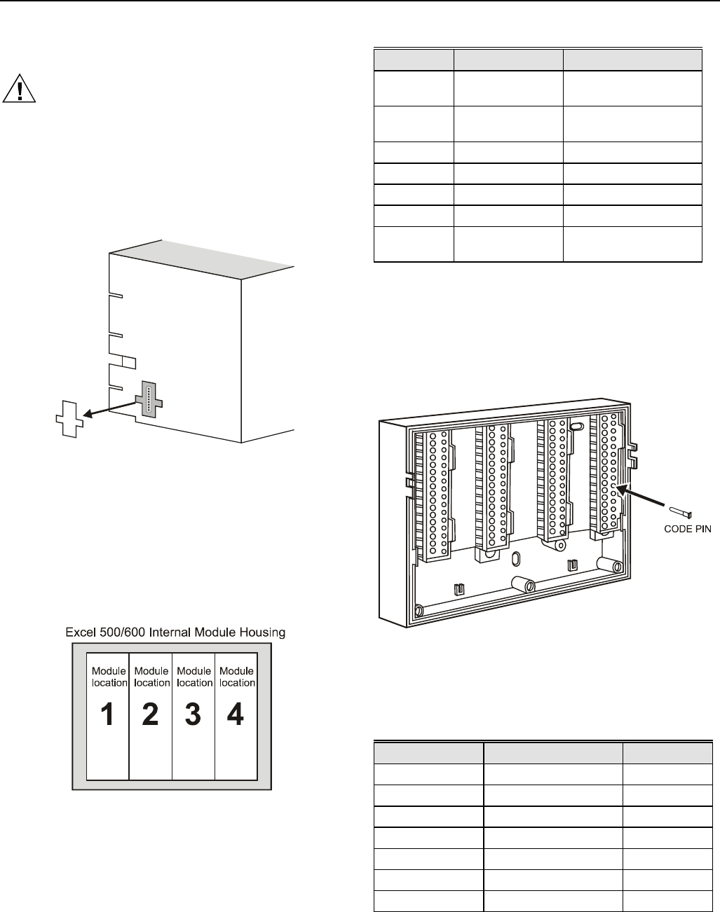
Coding the Terminal Block (not XCL5010)
The terminal block is coded with pins to prevent mixing the
module types during commissioning or servicing. Mixing the
modules can damage them.
You can code the terminal block by inserting pins into
designated location holes on the terminal block in the base.
Fig. 7. Inserting the code pin in the terminal block
Table 2 shows the coding pin positions for the individual
module types:
Table 2. Code pin position by module type
Module Type Pin position
CPU XC5010C, XC6010 08
Power supply XP502 06
AI XF521A, XF526 07
AO XF522A, XF527 11
DI XF523A 09
DO XF524A, XF529 10
3-position output XF525A 12
Fig. 6. Internal module numbering
Table 1 shows the plug-in location to which each module may
be assigned:
NOTE: Distributed I/O modules are coded differently. See
Distributed I/O Product Data (EN0B-0090GE51).
7 EN1R-1047GE51 R0902