


EXCEL 500/600 INSTALLATION INSTRUCTIONS
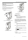
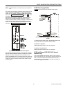
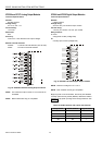
Fig. 50. Excel 600 submodule mounting location
For information pertaining to system bus baud rates and
termination switch settings, see section "C-Bus Termination
(Excel 600)" on page 38.
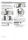
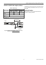
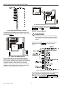
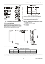
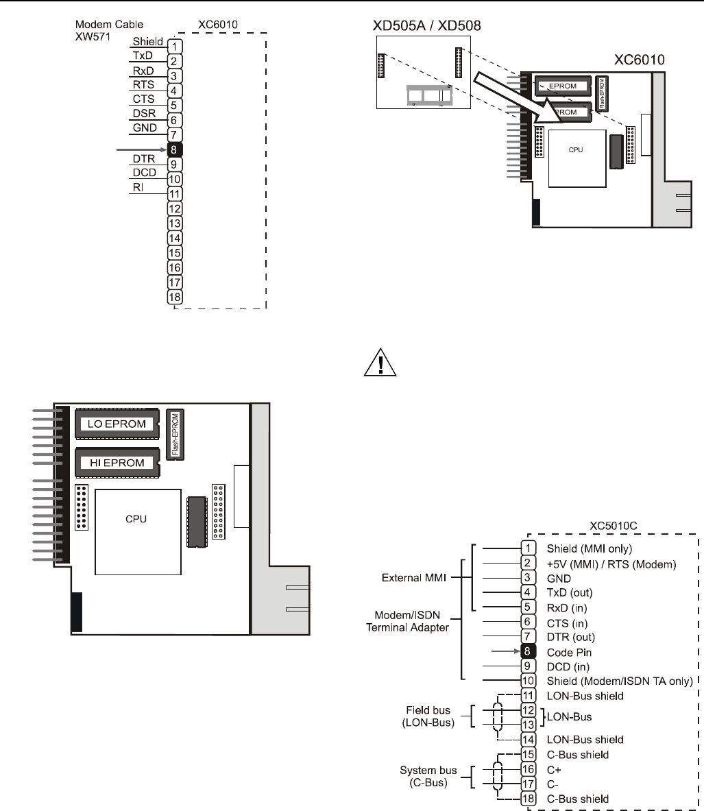
Fig. 48. Excel 600 CPU modem connection
The XC6010 has 2 EPROMs for the operating system and
one flash EPROM for the application software. Their locations
are shown in Fig. 49.
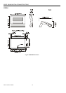
Fig. 49. Excel 600 EPROM locations
Communication between several Excel 600 controllers is
possible only if the system bus submodule is plugged into
every computer module printed circuit board. This submodule
must be installed when joining several controllers, when
connecting a modem, or when monitoring via a central.
XD505A or XD508 can be used for local bus communication,
XDM506 is used for modem communication. A stand-alone
controller can be operated without a submodule.
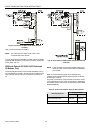
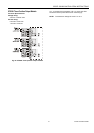
XC5010C Computer Module
CAUTION
Do not unplug the computer module with the power
still connected, since this could destroy the module.
First, switch S1 on the power supply module to the 0
position.
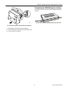
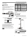
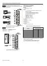
The XC5010C computer module contains both the system
bus and the field bus. Fig. 51 shows the pin-out of the
module.
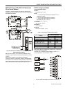
Fig. 51. Excel 500 CPU module pin-out
The system bus is connected to terminal 16 (C+) and terminal
17 (C-). The field bus (L
ONWORKS bus) is connected to
terminals 12 and 13. The L
ONWORKS bus is non-polarized, i.e.
there is no + or – pin. See section "LONWORKS Bus Wiring"
(page 36) and "System Bus (C-Bus)" (page 37) for more
information.
EN1R-1047GE51 R0902 24