


EXCEL 500/600 INSTALLATION INSTRUCTIONS
MOUNTING
Control Unit Installation
The Excel 500 and 600 controllers have the same housing
and can be installed two different ways:
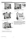
— Installation inside a control panel (see page 8).
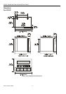
— Installation through a control panel door (see page 10).
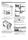
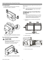
Fig. 1. Excel 500/600 panel door mounting
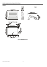
The Excel 500-XCL5010 can be mounted only on a DIN rail;
control panel door installation is not possible.
Fig. 2. Excel 500-XCL5010 DIN rail mounting
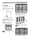
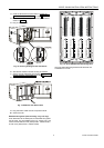
Excel 500/600 Housing Layout (not XCL5010)
A controller comprises from one to a maximum of five
housings. The housings may be fitted alongside one another
or, one above the other. Any combination is possible.
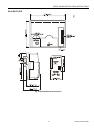
Fig. 3. Up to five housings can be connected together
When housings are alongside one another, a minimum
spacing of 1.5 in. (35 mm) should be taken into consideration
to enable the hinged cover to be opened. The maximum
spacing between housings is limited by tailor-made internal
bus cables as shown in Fig. 3.
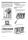
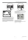
Excel 500/600 Internal Bus Wiring (not
XCL5010)
Each housing has four plug-in module locations. The
individual modules are connected by an internal bus in the
housing.
Configurations comprising more than one housing must have
the individual busses in the housings connected to one
another.
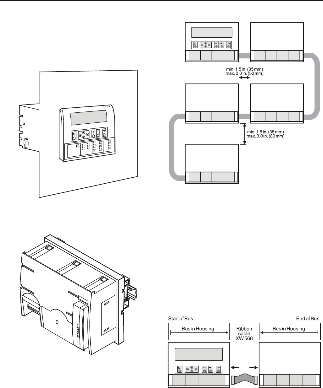
Fig. 4. Excel 500/600 bus wiring
The connection is made via tailor-made ribbon cables. Two
different types are available:
— Type XW568 3 in. (80 mm) long (for housings alongside
one another)
EN1R-1047GE51 R0902 6