


EXCEL 500/600 INSTALLATION INSTRUCTIONS
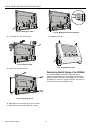
ELECTRICAL CONNECTIONS
When connecting the controller, both VDE, National Electric
Code NEC (or equivalent) and any local regulations con-
cerning grounding and zero voltage must be observed.
Electrical work should be carried out by a qualified electrician.
Under no circumstances should spare controller terminals be
used as wiring support points. Doing so could damage the
modules.
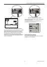
The electrical connections must be made at the terminal
blocks. The corresponding connection diagrams are on the
individual modules.
WARNING
Switch power OFF before making connections to or
removing connections from terminals to avoid
electrical shock or equipment damage.
IMPORTANT (FOR EUROPE, ONLY)
To comply with CE requirements, devices with a
voltage in the range of 50...1000 Vac or
75...1500 Vdc which are not provided with a supply
cord and a plug or with other means for
disconnection from the supply having a contact
separation of at least 3 mm in all poles, must have
the means for disconnection incorporated in the
fixed wiring.
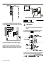
Cable Routing
The minimum distance to power mains cables is 0.4 in. (10
mm) for shielded cable and 4 in. (10 cm) for unshielded cable.
All low-voltage signal and output cables should be regarded
as communication circuits in accordance with VDE 0100 and
VDE 0800 (or NEC or other equivalent), and should therefore
be routed separately from mains cables.
Joining sensor cables should be avoided.
Shielding Input / Output Module and Power
Supply Cables
Shielding input and output module and power supply cables
is not necessary if the general guidelines for cable routing are
observed. If, in certain cases, the routing guidelines cannot
be observed, then shielded cable must be used.
The shield must not be terminated at a controller; instead, to
avoid ground loops, the shield must be grounded (at only one
end) at the control panel.
To prevent ground loops, shielding of input/output cables
leading to peripheral devices must be grounded only at the
control panel end.
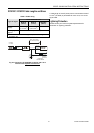
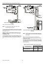
Shielding of Data-Transmitting Cables
Connect the shield of the system bus (C-Bus) to system
ground on both ends. Each end of the shield on the system
bus should be connected to the system ground terminal of the
respective computer module. Do not connect it to the control
panel earth or any other earth ground points.
NOTE: The L
ONWORKS bus must not be shielded on the
CPU side.
To connect remote operator interface units, ready-made
cables are available (XW565; XW582, XW583, etc.) with the
shield already connected to the computer module plug end.
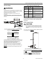
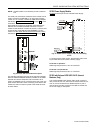
Grounding (XC5010C / XC6010, only)
The controller should be grounded using as short a cable as
possible (minimum 16 AWG [1.5 mm²]) between the control
panel and the terminal block of the power supply module.
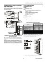
System Ground
WARNING
High voltage
Risk of electrical shock or equipment damage.
The controller's system ground must have no
connection with the control cabinet ground!
NOTE: A document providing additional information on
system grounding (if required) is available via the
Honeywell Technical Assistance Center (TAC) or, for
Honeywell employees, on the Docu Server under:
http://web.ge51.honeywell.de/dep/mc/TAC_Tips.
RFI Suppression
Honeywell actuators are RFI (Radio Frequency Interference)
suppressed as standard in accordance with VDE 0871/B and
VDE 0875/N.
EN1R-1047GE51 R0902 20