


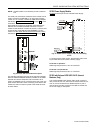
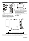
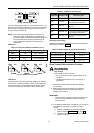
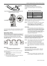

Fig. 69. Transformer example
Use quick-acting backup fuse 10 A (or automatic H16 or L16)
to protect transformer primary side. On the primary side of the
CRT 2, there is a fusible output of type M 0.315 A (T) 250 V
for the purpose of fine fusing.
NOTE: When selecting the appropriate transformer, con-
sider the number of Distributed I/O modules (see
worst-case power consumption information below) to
be used as well as the power requirements of all
active sensors and actuators connected to the
transformer.
CRT-Series
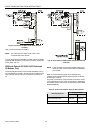
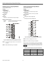
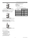
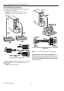
Table 12. Overview of CRT Series AC/DC current
Transformer max. AC current max. DC current
CRT 2 2 A 0.5 A = 500 mA
CRT 6 6 A 1.3 A = 1300 mA
CRT 12 12 A 2.5 A = 2500 mA
Fig. 70. AC/DC current graphs
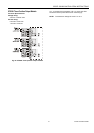
1450 Series
All transformers of the 1450 series are designed for 50/60 Hz
AC and have insulated accessory outputs. The transformers
include built-in fuses, line transient/surge protection and AC
convenience outlets and meet NEC class 2 requirements.
EXCEL 500/600 INSTALLATION INSTRUCTIONS
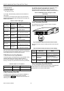
Table 13. 1450 Series transformers
Part #
1450 7287
Primary side Secondary side
-001 120 Vac 24 Vac, 50 VA
-002 120 Vac
2 x 24 Vac, 40 VA and 100 VA
from separate transformer
-003 120 Vac
24 Vac, 100 VA and 24 Vdc
600 mA
-004 240/220 Vac 24 Vac, 50 VA
-005 240/220 Vac
2 x 24 Vac, 40 VA and 100 VA
from separate transformer
-006 240/220 Vac
24 Vac, 100 VA and 24 Vdc
600 mA
Standard Transformers
Standard commercially available transformers must fulfill the
specifications stated in Table 14.
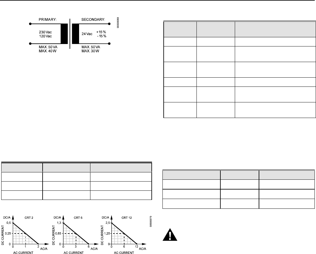
Table 14. Requirements for standard transformers
Output voltage Impedance AC current
24.5 Vac to 25.5 Vac
≤ 1.15 ohms
max. 2 A
24.5 Vac to 25.5 Vac
≤ 0.40 ohms
max. 6 A
24.5 Vac to 25.5 Vac
≤ 0.17 ohms
max. 12 A
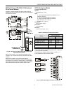
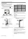
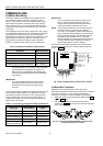
Screw Terminal Block Installation Procedure
WARNING
High Voltage
Risk of death or electrical shock.
— Do not connect line power supply directly to the
terminals.
— Insulate devices with 120 Vac / 230 Vac by a
transformer.
1. Make sure that the power supply of the cabinet is
disconnected.
2. Make sure that the power supply of the cabinet is
disconnected and the communication module is
plugged in the housing.
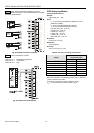
IMPORTANT
When installing a separate external transformer, do
not connect the cabinet ground to the controller
system ground.
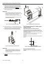
3. If the distance between the controller and an actuator or
sensor with 24 Vac supply is greater than 550 ft
(170m):
a) Choose a transformer from the transformers
listed in section "Power Supply" on page 32.
b) Connect the chosen transformer directly to the
actuator or sensor.
33 EN1R-1047GE51 R0902