


EXCEL 500/600 INSTALLATION INSTRUCTIONS
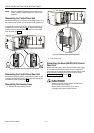
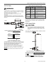
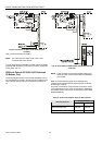
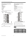
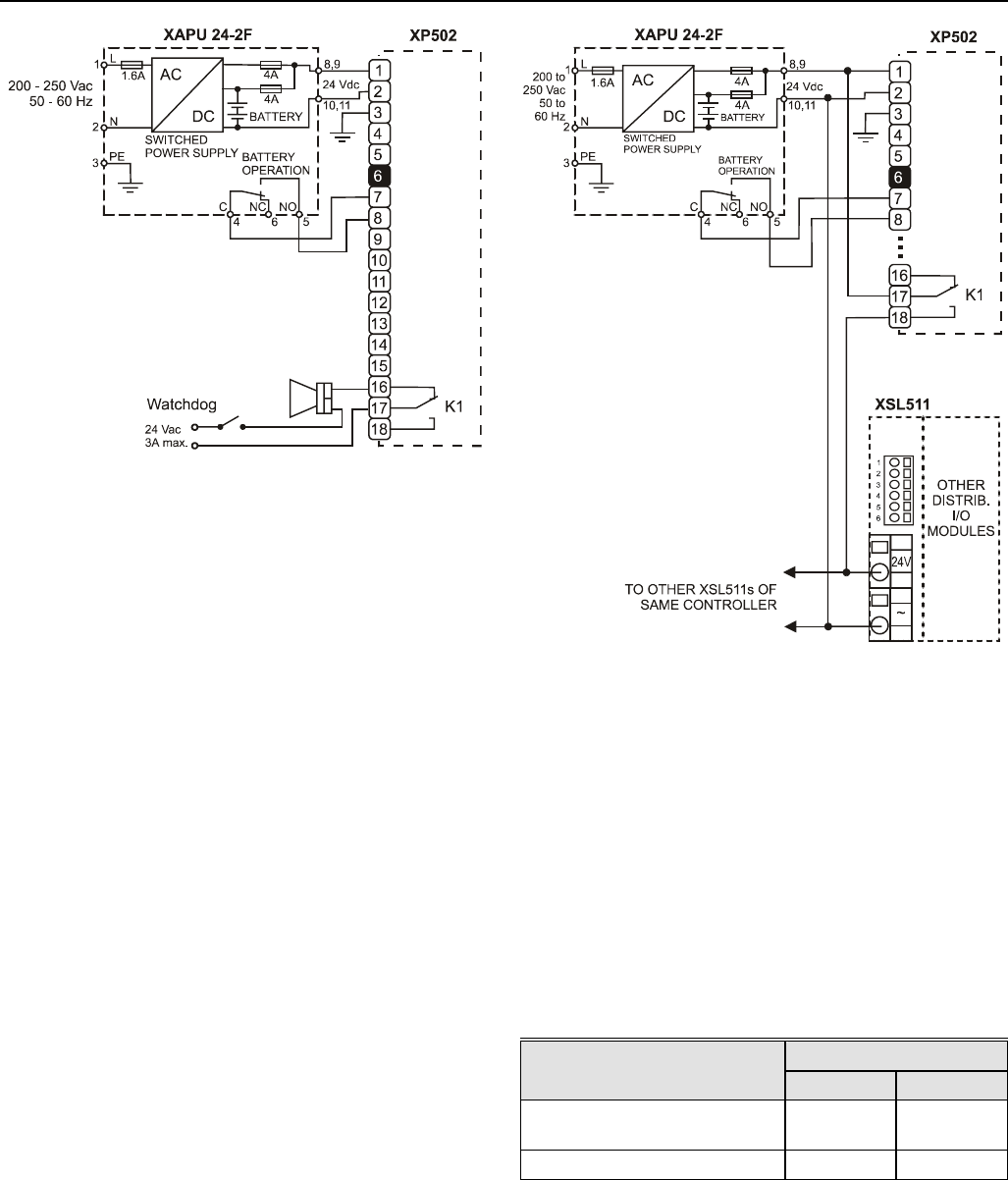
Fig. 54. Connection of XAPU 24-2F UPS (internal
modules)
LED (L3) shows operation by battery.
NOTE: The output from the XAPU 24-2F must not be
connected with other devices.
The fully-equipped Excel 500/600 controller will be completely
supported with the battery for at least 15 minutes, without the
mains power 230 Vac.
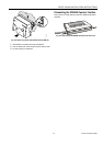
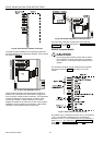
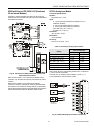
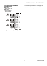
XP502 with External UPS XAPU 24-2F (Distributed
I/O Modules, Only)
The wiring diagram below is for Excel 500 installations using
only Distributed I/O modules. No internal I/O modules may be
used. No other devices may be connected to the XAPU 24-
2F.
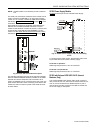
Fig. 55. Connection of XAPU 24-2F UPS (Distributed I/O
modules)
NOTE: There must be no connection between GND of the
XC5010C CPU module and the GND of Distributed
I/O modules.
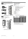
Relay K1 insures that the supply of the Distributed I/O
modules will be switched OFF by switching OFF the XP502
Power Supply module.
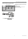
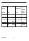
The power consumption of the Excel 500 controller is shown
in the table below. For the power consumption of Distributed
I/O modules, please refer to the corresponding Product Data
(EN0B-0090GE51)
Table 6. Power consumption of Excel 500 controller
Devices powered
Supply voltage
24 Vdc 28.8 Vdc
XP502, XC5010C,
XI581 (backlight ON)
170 mA 155 mA
XP502, XC5010C 140 mA 130 mA
EN1R-1047GE51 R0902 26