


Operation
312350E 7
Operation
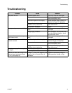
Pressure Relief Procedure
The system pressure must be manually relieved to
prevent the system from starting or dispensing
accidentally. Follow this pressure relief procedure
whenever you are instructed to:
• relieve pressure.
• check or service any system equipment.
• install or clean nozzle.
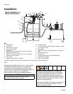
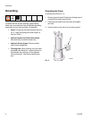
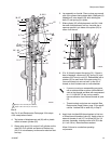
For the following instructions, see F
IG. 1.
1. Shut off hydraulic power supply.
2. Close supply line shut-off valve (L).
3. Open dispensing valve to relieve pressure.
4. Open pump outlet drain valve. Have a container
ready to catch drainage.
5. Close return line shut-off valve (H).
If you suspect the nozzle or hose is completely clogged
or that pressure has not been fully relieved after
following steps 1-5 above, very slowly loosen the hose
end coupling to relieve pressure, then clear obstruction.
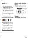
Before Starting Pump
• Check hydraulic fluid level in hydraulic power supply
before each use. Add fluid as necessary to fill the
lines.
• Flush pump before using it for the first time to
remove the light oil that was left in after factory test-
ing to protect pump from corrosion. Be sure solvent
used is compatible with the fluid to be pumped and
the pump’s wetted parts. See Technical Data, page
20. Flush until clean solvent comes out of hose.
Leave drain valve open until you are ready to
dispense again.
COMPONENT RUPTURE HAZARD
Overpressurizing any component can result in
serious injury or property damage as a result of
rupture, fire, and/or explosion.The maximum working
pressure of each component in the system may not
be the same. To reduce the risk of overpressurizing
any component in the system:
• Be sure you know the maximum working
pressure of each component.
• Never exceed the maximum working pressure of
the lowest rated component in the system.
• Do not exceed the maximum pump cycle rate.
• The pump has a rated ratio of 10:1. However, it is
capable of reaching stall pressures equal to 12.5
times the hydraulic input pressure. To calculate
the fluid output pressure, multiply the hydraulic
pressure shown on the hydraulic control module
gauge by 12.5.
For example:
600 psi hydraulic x 12.5 = 7500 psi fluid output
4.14 MPa hydraulic x 12.5 = 51.8 MPa fluid
output
41.4 bar hydraulic x 12.5 = 5.18 bar fluid output
• Regulate hydraulic pressure to the pump so that
no fluid line component or accessory is
overpressurized.