


Installation
4 312350E
Installation
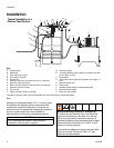
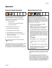
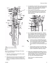
Key:
A Follower plate
B Weep tube
C Fluid outlet line (to gun)
D Drain valve (required)
E Ground wire
F Hydraulic return line, minimum 3/4 inch I.D. (required)
G Hydraulic outlet, 3/4” npt (f)
H Return line shut-off valve, minimum 3/4 inch (required)
J Hydraulic inlet, 3/4” npt (m)
K Tee, 3/4” npt
L Supply line shut-off valve (required)
M *Pressure gauge
N *Pressure reducing valve (required in systems over 600
psi [4.1 MPa, 41 bar])
P Accumulator
Q *Flow control valve (required in systems over 3 gpm [11
lpm])
R Hydraulic supply line
SCheck valve
T Variable volume pressure compensated pump
U Hydraulic power supply
V Drain line, accumulator
*Included in Hydraulic Fluid Control Kit 247538 or 247705, which can be ordered separately.
FIG. 1
Although the installation shown in F
IG. 1 is only a guide
for selecting and installing system components and
accessories, some of the equipment is required, as
noted in the key. For assistance in designing a system to
suit your needs, contact your Graco distributor.
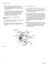
Mount pump to suit the type of installation planned.
ti0477a
Typical Installation of a
Suction Feed System
U
T
S
R
Q
P
N
M
L
K
J
H
G
F
D
C
B
A
E
CAUTION
Do not operate pump without it being securely
mounted to a drum cover or support.
Maximum Working Pressure of Accessories
To reduce the risk of serious injury including fluid
injection and splashing in the eyes or on the skin
which may be caused if component ruptures, all
accessories added to the reciprocator power supply
side must have at least 600 psi (4.1 MPa, 41 bar)
maximum working pressure.
All accessories added to the pump fluid outlet side
must have at least 7500 psi (51 MPa, 517 bar)
maximum working pressure.