


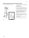
Reciprocator Repair
312350E 15
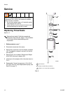
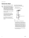
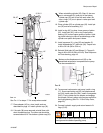
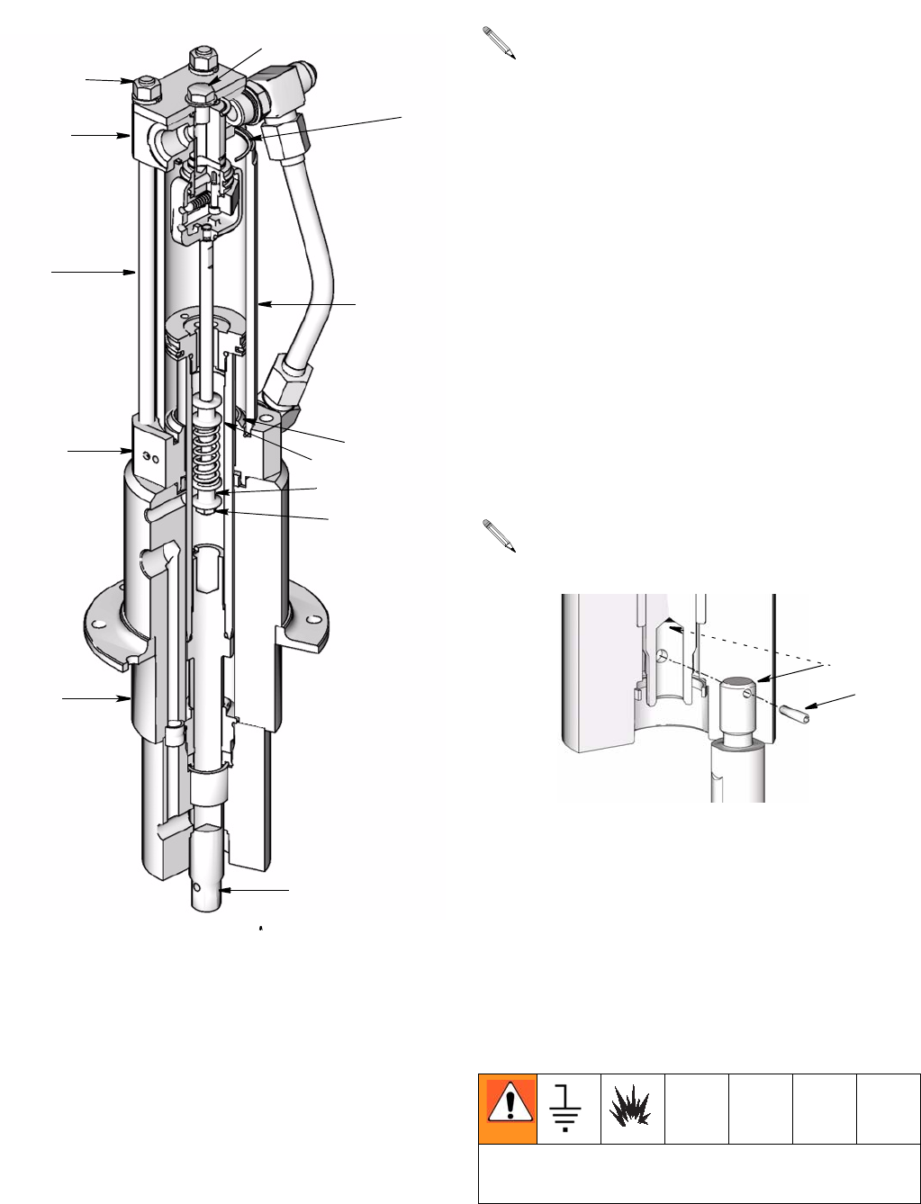
FIG. 11
See F
IG. 11 for steps 17- 24 except where noted.
17. Place adapter (43) in a vise. Install seals as
described on page 10. Install cylinder cap (32).
18. If tie rods (38) were removed, reinstall them with
short threaded end up. The other end should be
screwed about 9/16” into bottom cylinder cap (32).
19. Place cylinder (25) on cylinder cap (32). Install pis-
ton (22) and valve assembly (31).
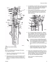
20. Install o-ring (49*) in deep, lower groove of piston
(22). Install seal (23*) over o-ring. Install piston
bearing (24*) around upper groove of piston. Hold-
ing piston bearing in place to avoid damage, slide
cylinder over piston and press it down.
21. Install capscrew (3), o-ring (39) and washer (2).
Install lockwashers (37) and nuts (36). Torque nuts
to 28 to 32 ft-lb (38 to 43 N.m).
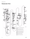
22. Reinstall fluid tube (45) and fittings (1). Torque fit-
tings to 28 to 32 ft-lb (38 to 43 N.m). See Reciproca-
tor Parts drawing, page 18.
.
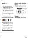
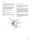
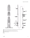
FIG. 12
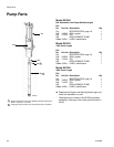
23. To reconnect reciprocator and pump, install o-ring
(17). Screw connecting rod (35) into displacement
rod (34). Install cotter pin (204). Install a new gasket
(202*). Push cylinder up into adapter and engage
the threads. Screw in pump using a strap wrench for
the final tightening (See F
IG. 12 and Pump Parts,
page 20).
24. Connect hydraulic supply and return hoses to fit-
tings (5, 60).
3, 39, 2
36, 37
31
13*
25
32
18
20
13*
17
38
43
35
ti10605a
When reinstalling cylinder (25), Step 19, be sure
port in valve spool (31) and port in the bottom
cylinder cap (32) are in line with each other. Be
sure o-rings (13*) are in place in valve spool and
cylinder cap.
Make sure the displacement rod (35) on the
assembled reciprocator is exposed so the pump
can be connected to it.
To reduce risk of static sparking, be sure to recon-
nect ground wire before operating pump.
35
204
ti10610a