


Installation
312350E 5
Pump Accessories
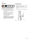
Follower Plate (A): ensures a good prime. Place
follower plate on grease and rotate while pressing firmly
to level material. Order part number 247700 for 60# and
90# automatic lube pump modules; 247701 for 120#
refinery reservoir; or 247702 for 400# refinery reservoir.
Pump Outlet Drain Valve (D): helps relieve fluid
pressure in pump when pump is shut off. Install valve
close to pump fluid outlet. Order valve, Part No. 111229.
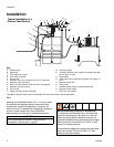
Hydraulic Power Supply
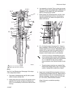
See FIG. 1.
The hydraulic power supply system (U) must have a
pressure reducing valve and a pressure-compensated
flow control. A flow control valve (Q) is required to limit
the incoming flow to the reciprocator to a maximum of 3
gpm (11 lpm).
Hydraulic Lines
Shut-off Valves (H, L): installed on the hydraulic supply
and return lines. Order Part No. 108537 and 112578.
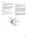
Drain Line: Monitor the weepage of hydraulic fluid or
lubricant. If it seems excessive or increases suddenly,
the reciprocator/pump seals may need to be changed.
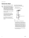
See F
IG. 2.
F
IG. 2
Hoses: Use a minimum 1/2 inch supply line (R) and
minimum 3/4 inch return line (F) on the reciprocator.
Contact your Graco representative for details of line
sizing.
Pressure Reducing Valve (N): circulates excess
hydraulic fluid pressure back to the hydraulic power
supply. Install this valve (N) in the hydraulic supply line
with a drain hose (W) teed into the hydraulic return line
(F). Limit supply pressure to a maximum 600 psi (4.1
MPa, 41 bar).
Accumulator (P): reduces hammering effect caused by
the motor when it reverses direction.
Fluid-filled Pressure Gauge (M), Part No. 112567:
monitors hydraulic pressure to the reciprocator during
startup. See F
IG. 1. Use the gauge for initial adjustment
of the reciprocator. It can be removed after adjustment.
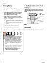
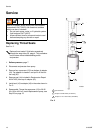
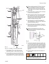
Pump Outlet Drain Valve
• A pump outlet drain (D) is required in your system.
This valve helps relieve pressure in the displace-
ment pump and hose when shutting down system
and in case of a clogged outlet hose. Install valve
close to pump outlet.
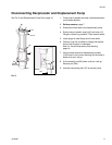
• Mount pump securely so it cannot move around
during operation. Failure to do so could result in
personal injury and/or equipment damage.
Limit Fluid Flow to Reciprocator
To reduce the risk of overpressurizing the hydraulic
reciprocator which could cause a rupture and serious
injury, including fluid injection, a hydraulic system
must have a means to limit the incoming fluid flow to
the reciprocator to a maximum of 3 gpm (11 lpm) and
600 psi (4.1 MPa, 41 bar). See description below.
Pressure gauge (M), pressure reducing valve (N)
and a flow control valve (Q) are included in the
Hydraulic Fluid Control Kit 247538 or 247705,
which can be ordered separately.
ti10602a