7
Combi HP thermostatic mixer shower
Exposed
Note: The outlet of the shower must not be
connected to anything other than the hose and
showerhead supplied.
DO NOT use jointing compounds on any pipe
fittings for the installation.
DO NOT
solder fittings near of the shower unit,
as heat transfer can damage components.
Note: Suitable isolating valves (complying with
Water Regulations) must be fitted on the hot
and cold water supplies to the shower as an
independent means of isolating water supplies
should maintenance or servicing be necessary.
When connecting pipework avoid using tight
90° elbows. Swept or formed bends will give the
best performance.
IMPORTANT:
The water circuit should be
installed such that the flow is not significantly
affected by other taps and appliances being
operated elsewhere on the premises. Water
pressure must not fall below specification of
the shower.
Note: The hot water pipe entry must be on the
left.
Rising and falling supplies
Having decided on the position of the shower
and direction of pipe entry, complete the
pipework to the shower area.
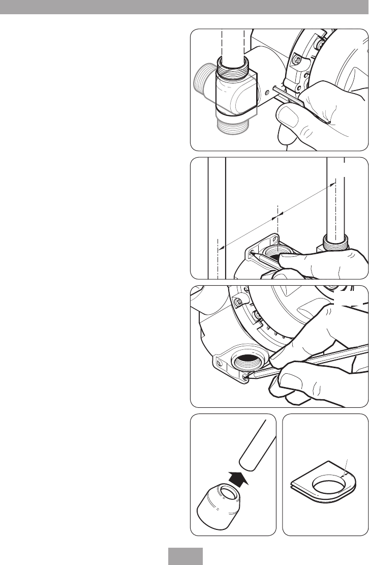
Note: The final separation between pipe
centres needs to be about 153 mm but absolute
accuracy is not needed as the inlet elbows are
adjustable between 146 mm and 160 mm.
Flush pipework to clear the system of all
debris and check for leaks.
IMPORTANT:
The inlet elbows contain check
valves that may be damaged if debris is not
flushed through prior to fitting.
Where this is not possible refer to the
‘flushing
procedure’ on page 20.
Clip the pipework to the wall surface so that the
pipe centres are 21 mm off the wall.
Offer the valve, together with the inlet elbows,
to the pipework. Make sure the inlet elbow grub
FITTING THE SHOWER TO THE WALL - EXPOSED
FITTING THE SHOWER TO THE WALL
T00227
Fig.8
T00228
=
=
Fig.9
T00229
Fig.10
T00230
T00231
/RQJ
VLGH
Fig.11 Fig.12


