


14
Combi HP thermostatic mixer shower
T00251
T00253
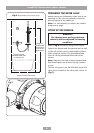
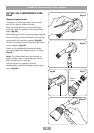
Seal tight up
to shroud
T00252
Fig.31
Fig.32
Fig.33
shower from the top (falling), the bottom (rising)
or the rear.
Mark the route of the incoming and outgoing
pipework.
Note: The final separation between pipe
centres needs to be about 153 mm but absolute
accuracy is not essential as the inlet elbows are
adjustable between 146 mm and 160 mm.
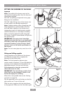
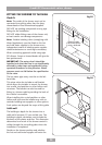
Remove the plaster and brickwork to the depth
shown (fig.29). Where applicable, chase out
any additional areas of the wall for the pipework
to either the bulkhead or fixed head.
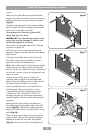
Offer the mounting bracket up to the wall and
mark the two plain fixing holes (fig.30). Drill
and plug then screw bracket to the wall.
Note: The valve can be fitted to the mounting
bracket if required or secured directly to the wall
with the screws supplied.
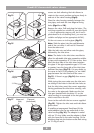
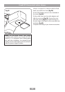
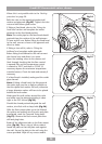
If installing a fixed head, the outlet adaptor
needs to be fitted into the top outlet hole in the
valve housing (fig.16). The adaptor is sealed
with an ‘O’ ring. Make sure the adaptor is fitted
with the hose end (fig.17) in the valve housing.
Fit the blanking plug into the bottom outlet hole
using an ‘O’ ring to seal it.
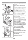
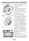
If fitting a bulkhead outlet, the outlet adaptor
needs to be fitted into the bottom outlet hole in
the valve housing. The adaptor is sealed with an
‘O’ ring. Make sure the adaptor is fitted with the
hose end in the valve housing (fig.17).
Fit the blanking plug into the top outlet hole
using an ‘O’ ring to seal it (fig.18).
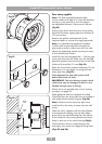
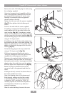
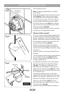
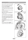
Make sure the inlet elbows are positioned
correctly. Offer the valve up to the mounting
bracket or wall surface, and secure using the
screws provided (fig.31).
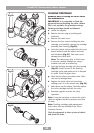
Complete the pipework to the shower marking
off the length to enter the elbows. Remove the
valve and cut the pipes to length.
Flush pipework to clear the system of all debris
and check for leaks.
IMPORTANT:
The inlet elbows contain check
valves that may be damaged if debris is not
flushed through prior to fitting.