


10
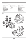
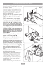
Combi HP thermostatic mixer shower
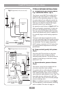
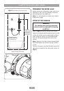
Rear entry supplies
Note: The final separation between pipe
centres needs to be about 153 mm but absolute
accuracy is not essential as the inlet elbows
are adjustable between 146 mm and 160 mm
(fig.23).
Using a spirit level, mark the route of incoming
hot and cold water supply pipes at a distance of
153 mm centres.
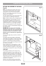
Remove the plaster and brickwork to the
required depth to conceal the supply pipework.
Note: It is advisable that pipework installed
in solid walls be provided with enough free
play inside a cavity to allow entry into the inlet
elbows for tightening, before securing the valve
to the finished wall surface.
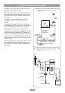
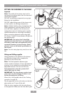
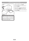
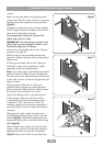
Install the hot and cold pipework — the hot pipe
must enter from the left. Make sure the finished
pipework projects from the front face of the tiled
surface of the wall by 9.5 mm (fig.24).
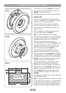
Allow for two circular recesses measuring 32 mm
diameter by 14 mm depth, to accept the rear
entry pipe trims (fig.23).
Flush pipework to clear the system of all
debris and check for leaks.
IMPORTANT:
The inlet elbows contain check
valves that may be damaged if debris is not
flushed through prior to fitting.
Where this is not possible refer to the
‘flushing
procedure’ on page 20.
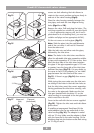
Make good the wall and complete the tiling.
Check that the rear entry pipe trims are sealed in
with either silicon sealant or grout (fig.24).
Note: Failure to fit the rear entry pipe trims
could result in the entry of water into the wall
cavity.
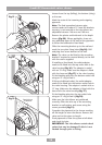
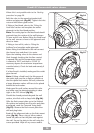
Offer the valve, together with the inlet elbows,
to the pipework making sure the inlet elbow
grub screws are slack allowing the inlet elbows
to be rotated to the correct position and move
freely in and out of the valve housing (fig.8).
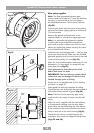
Check that the valve is central between the
two pipes, then mark two diagonal fixing holes
(figs.25 and 26).
T00242
T00244
9.5
mm
Pipe
trim
Inlet
nut
T00243
32 m
m
dia
.
9.5 mm
153 m
m approx
Fig.22
Fig.23
Fig.24