13
Combi HP thermostatic mixer shower
FITTING THE SHOWER TO THE WALL - BUILT-IN
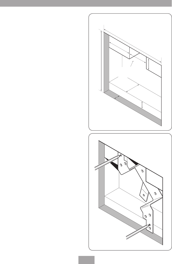
FITTING THE SHOWER TO THE WALL
Opening needs
to be at the bottom
if using a bulkhead
200
m
m
10 -
12.5
m
m
48 m
m
50 mm
35 m
m
77.5 m
m
65
mm
220 mm
T00249
Fig.29
T00250
Fig.30
Flush fit
Note: The outlet of the shower must not be
connected to anything other than the hose,
showerhead or fixed showerhead supplied.
DO NOT
use jointing compounds on any pipe
fittings for the installation.
DO NOT
solder fittings near of the shower unit,
as heat transfer can damage components.
Note: Suitable isolating valves (complying with
Water Regulations) must be fitted on the hot
and cold water supplies to the shower as an
independent means of isolating water supplies
should maintenance or servicing be necessary.
When connecting pipework avoid using tight
90° elbows. Swept or formed bends will give the
best performance.
IMPORTANT:
The water circuit should be
installed such that the flow is not significantly
affected by other taps and appliances being
operated elsewhere on the premises. Water
pressure must not fall below the specification
of the valve.
The hot water pipe entry must be on the left-
hand side.
This mixer valve also includes a wall bracket
which allows the installer to mount the shower
into a solid, stud partition or other hollow wall
structures. The bracket can also be used for
fitting in a shower cubicle providing the back of
the cubicle is accessible.
When installing into a stud partition or other
hollow wall structure the installer may wish to
consider building rear supports or other options.
Such options are beyond the scope of this guide.
Solid wall
The building-in depth for the shower into a
solid wall is between 57 mm and 66 mm. The
building-in depth calculation must include the
thickness of the plaster and tiles. This dimension
determines how much of the shower control is
visible through the concealing plate when the
installation is completed.
Decide on the shower position and whether
the hot and cold water supplies will enter the


