


Heatilator • ICON DV-IDV Series • 4042-575 • Rev. S • 5/11 41
A. Wiring Requirements
NOTICE: This appliance must be electrically wired
and grounded in accordance with local codes or, in the
absence of local codes, with National Electric Code
ANSI/NFPA 70-latest edition or the Canadian Electric
Code CSA C22.1.
• Wire the appliance junction box to 110-120 VAC. This is
required for use of optional accessories (standing pilot
ignition) or proper operation of the appliance (Intellifi re
ignition).
• A 110-120 VAC circuit for this product must be protected
with ground-fault circuit-interrupter protection, in
compliance with the applicable electrical codes, when
it is installed in locations such as in bathrooms or near
sinks.
• Low voltage and 110 VAC voltage cannot be shared
within the same wall box.
WARNING! Risk of Shock or Explosion! DO NOT wire
110V to the valve or to the appliance wall switch. Incorrect
wiring will damage controls.
• This appliance is equipped with an Intellifi re control valve
which operates on a 3-volt system.
• Plug the 3-volt AC transformer into the appliance junction
box to supply power to the unit OR install two D cell
batteries (not included) into the battery pack before
use.
NOTICE: Batteries should not be placed in the battery
pack while using the transformer. Remove batteries before
using the transformer, and unplug the transformer before
installing the batteries. Battery polarity must be correct or
module damage will occur.
C. Optional Accessories Requirements
• This appliance may be used with a wall switch, wall
mounted thermostat and/or a remote control.
Wiring for optional Hearth & Home Technologies ap-
proved accessories should be done now to avoid re-
construction. Follow instructions that come with those
accessories.
13
13
Electrical Information
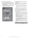
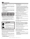
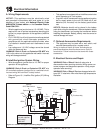
D. Electrical Service and Repair
WARNING! Risk of Shock! Label all wires prior to
disconnection when servicing controls. Wiring errors can
cause improper and dangerous operation. Verify proper
operation after servicing.
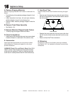
Ignitor
Flame
Sensor
Pilot Assembly
GRN
ORG
BLK
ORG
Control
Box
To
Junction
Box
Battery
Pack
3V
Adapter
BLK
BRN
RED
RED
WHT
Optional
SPST Wall Switch
or
Optional Remote
Valve
WHT
+
-
+
-
WHT
RED
GRN*
*
GRN wire only for
use with optional
wall switch
WSK-MLT
Figure 13.1 Intellifi re Pilot Ignition (IPI) Wiring Diagram
WARNING! Risk of Shock! Replace damaged wire with
type 105° C rated wire. Wire must have high temperature
insulation.
B. Intellifi re Ignition System Wiring
• Wire the appliance junction box to 110 VAC for proper
operation of the appliance.
WARNING! Risk of Shock or Explosion! DO NOT wire
IPI controlled appliance junction box to a switched circuit.
Incorrect wiring will override IPI safety lockout.
• Refer to Figure 13.1, Intellifi re Pilot Ignition (IPI) Wiring
Diagram.