


Heatilator • ICON DV-IDV Series • 4042-575 • Rev. S • 5/1128
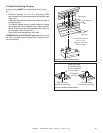
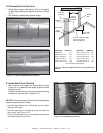
WALL
1-1/2 in.
(38 mm)
3 in.
(76 mm)
No combustible
framing to be
located within
shaded area.
2 x 4 or
2 x 6
header
Sheetrock
Air space clearance to
bottom and sides of
horizontal pipe must be
at least 1 in. (25 mm)
Framing should be
constructed of 2 X 4
lumber or heavier.
The center of the
framing hole is
1 in. (25mm) above
the center of the
horizontal vent pipe.
A*
Vent framing hole.
DO NOT PACK WITH
INSULATION OR
OTHER MATERIAL.
* To center of pipe.
10 in.
12 in.
Appliance A
IDV4833 64-1/8 in./1629 mm
IDV6247 68-5/8 in./1743 mm
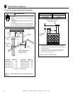
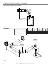
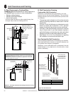
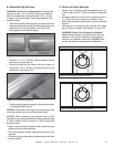
A. Pipe Clearances to Combustibles
WARNING! Risk of Fire! Maintain air space clearance to
vent. DO NOT pack insulation or other combustibles:
• Between ceiling fi restops
• Between wall shield fi restops
• Around vent system
Failure to keep insulation or other material away from
vent pipe may cause over heating and fi re.
8
8
Vent Clearances and Framing
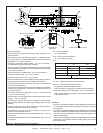
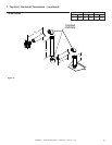
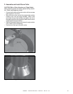
B. Wall Penetration Framing
Combustible Wall Penetration
Whenever a combustible wall is penetrated, you must
frame a hole for the wall shield fi restop(s). The wall shield
fi restop maintains minimum clearances and prevents cold
air infi ltration.
• The opening must be framed on all four sides using the
same size framing materials as those used in the wall
construction.
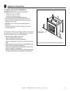
• SLP pipe - A wall shield fi restop must be placed on each
side of an interior wall. A minimum 1 1/2 in. (38 mm)
overlap of attached heat shields must be maintained.
• DVP pipe - A wall shield fi restop is required on one side
only on interior walls. If your local inspector requires a
wall shield fi restop on both sides, then both wall shield
fi restops must have a heat shield attached to them.
• See Section 10.I. & 10.J. for information for regarding
the installation of a horizontal termination cap.
Figure 8.2 Wall Penetration
Figure 8.1 Vent Pipe and Horizontal Venting Clearances To Com-
bustible Materials
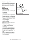
Non-Combustible Wall Penetration
If the hole being penetrated is surrounded by non-combus-
tible materials such as concrete, a hole with diameter one
inch greater than the pipe is acceptable.
Whenever a non-combustible wall is penetrated, the wall
shield fi restop is only required on one side and no heat
shield is necessary.
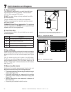
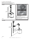
3 in. (76 mm)
top clearance
1 in. (25 mm)clearance
bottom & sides
1 in. (25 mm)
clearance
around vertical
sections
3 in. (76 mm)
top clearance
1 in. (25 mm)
clearance
bottom & sides
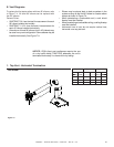
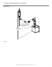
Heat
Shield
Wall
Shield
Firestop
Heat
Shield
WALL
Note: Heat shields MUST overlap by a minimum of 1-1/2 in. (38 mm). The
heat shield is designed to be used on a wall 4 in. to 7-1/4 in. (102 mm to
184 mm) thick. If wall thickness is less than 4 in. (102 mm) the existing heat
shields must be field trimmed. If wall thickness is greater than 7-1/4 in. (184
mm) a DVP-HSM-B will be required.