


43
Heatilator •
HEIR36, HEIR42, HEIR50 • 2285-900 Rev. D • 8/12
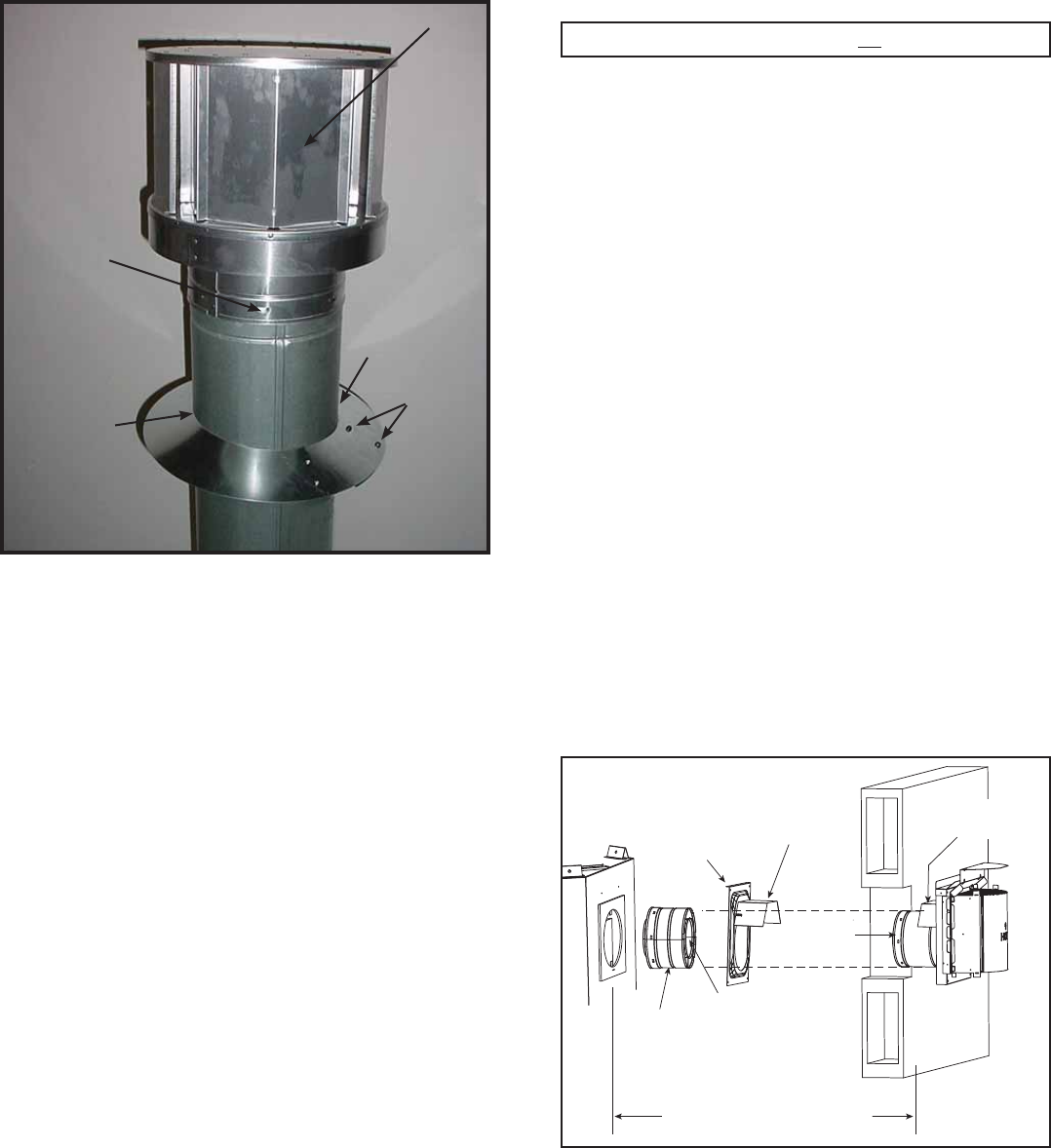
SCREWS
CAULK
STORM
COLLAR
(1 of 3)
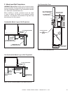
Figure 10.13
Figure 10.13
TERMINATION CAP
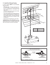
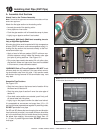
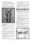
F. Install Vertical Termination Cap
• Attach the vertical termination cap by sliding the inner
collar of the cap into the inner fl ue of the pipe section
while placing the outer collar of the cap over the outer
fl ue of the pipe section.
• Secure the cap by driving three self-tapping screws
(supplied) through the pilot holes in the outer collar of
the cap into the outer fl ue of the pipe (see Figure 10.13).
Important Notice: Heat shields may not be fi eld constructed.
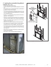
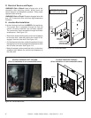
G. Heat Shield Requirements for Horizontal
Termination
WARNING! Risk of Fire! To prevent overheating and fi re,
heat shields must extend through the entire wall thick-
ness.
• DO NOT remove the heat shields attached to the
wall shield fi restop and the horizontal termination cap
shown in Figure 10.14.
• Heat shields must overlap 1-1/2 in. (38 mm) mini-
mum.
There are two sections of the heat shield. One section
is factory-attached to the wall shield fi restop. The other
section is factory-attached to the cap. See Figure 10.20.
If the wall thickness does not allow the required 1-1/2 in.
(38 mm) heat shield overlap when installed, an extended
heat shield must be used.
• If the wall thickness is less than 4 in./102 mm (DVP),
the heat shields on the cap and wall shield fi restop
must be trimmed. A minimum 1-1/2 in. (38 mm) overlap
MUST be maintained.
• Use an extended heat shield if the fi nished wall thickness
is greater than 7-1/4 in. (184 mm).
Note: When using termination caps with factory-supplied
heat shield attached, no additional wall shield fi restop is
required on the exterior side of a combustible wall.
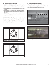
H. Install Horizontal Termination Cap
WARNING! Risk of Fire! The telescoping fl ue section of
the termination cap MUST be used when connecting vent.
• 1-1/2 (38 mm) minimum overlap of fl ue telescoping
section is required.
Failure to maintain overlap may cause overheating and
fi re.
• Vent termination must not be recessed in the wall. Siding
may be brought to the edge of the cap base.
• Flash and seal as appropriate for siding material at
outside edges of cap.
• When installing a horizontal termination cap, follow
the cap location guidelines as prescribed by current
ANSI Z223.1 and CAN/CGA-B149 installation codes
and refer to Section 6 of this manual.
CAUTION! Risk of Burns! Local codes may require in-
stallation of a cap shield to prevent anything or anyone
from touching the hot cap.
NOTICE: For certain exposures which require superior
resistance to wind-driven rain penetration, a fl ashing kit is
available. When penetrating a brick wall, a brick extension
kit is available for framing the brick.
• The extended heat shield may need to be cut to length
maintaining suffi cient length for a 1-1/2 in. (38 mm)
overlap between heat shields.
• Attach the extended heat shield to either of the existing
heat shields using the screws supplied with the extended
heat shield. Refer to vent components diagrams in the
back of this manual.
• Rest the small leg on the extended heat shield on top
of the pipe section to properly space it from the pipe
section.
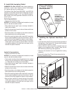
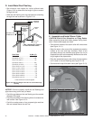
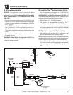
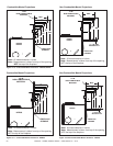
Figure 10.14 Venting Through the Wall
INTERIOR
HEAT SHIELD OR
EXTENDED
HEAT SHIELD
WALL SHIELD
FIRESTOP
HEAT SHIELD
1-1/2 IN. (38 MM) MIN.
OVERLAP
SHEATHING
VENT DEPTH FROM BACK OF APPLIANCE TO
OUTSIDE SURFACE OF EXTERIOR WALL
(SEE CHART BELOW)
SLIP SECTION
CAN BE EXTENDED
INNER VENT
OUTER VENT
EXTERIOR