


16
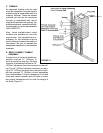
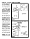
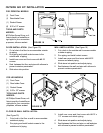
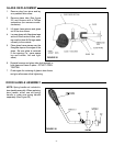
FIGURE 20
FOR LEG MODELS
(1) Front Cover
(1) Rear Intake Cover
(1 ) Rodent Screen
(4) 8-32 x 1/2" screws
TOOLS AND PARTS
NEEDED:
#2 Phillips Screw Driver, suf-
ficient quantity of metalflex or
rigid pipe for your connection
purposes, silicone sealant.
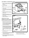
FLOOR OR WALL INSTALLATION:
(See Figure 20)
1. Cut a hole in the floor or wall to accommodate
outside air piping.
2. Run piping and install rodent screen to the
outside end of piping.
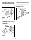
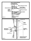
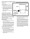
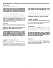
FIGURE 19
WALL INSTALLATION: (See Figure 19)
1. Cut a hole in the outside wall to accommodate
outside air piping.
2. Run piping and install rodent screen.
3. Install rear cover and front cover with #8-32
screws and attach piping.
4. Slide stove into position and adjust piping.
5. Seal between the wall and pipe with silicone to
prevent moisture penetration.
FOR PEDESTAL MODELS
(1) Front Cover
(1) Rear Intake Cover
(1 ) Rodent Screen
(6) 8-32 x 1/2" screws
TOOLS AND PARTS
NEEDED:
#2 Phillips Screw Driver, suf-
ficient quantity of metalflex or
rigid pipe for your connection
purposes, silicone sealant.
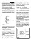
OUTSIDE AIR KIT INSTALLATION
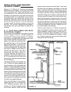
FLOOR INSTALLATION: (See Figure 19)
1. Cut a hole in the floor to accommodate outside
air piping.
2. Run piping and install rodent screen to the
outside end of piping.
3. Install rear cover and front cover with #8-32
screws.
4. Seal between the floor and pipe with silicone to
prevent moisture penetration.
5. Slide stove into position.
3. Install rear cover and front cover with #8-32 x
1/2 screws and attach piping.
4. Slide stove into position and adjust piping.
5. Seal between the floor and pipe, or wall and pipe
with silicone to prevent moisture penetration.