


Heat & Glo LifeStyle Collection • Twilight-II • 2087-900 Rev. G • 12/05 9
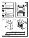
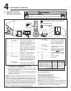
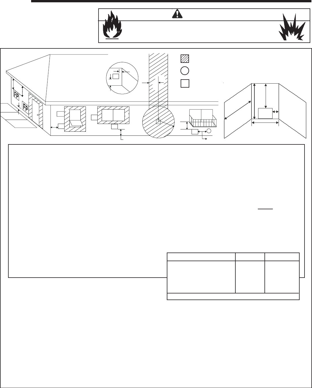
Termination Locations
4
___________________________________________________________________________
___________________________________________________________________________
___________________________________________________________________________
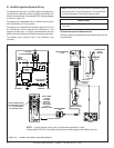
FP
= APPLIANCE OPENING
X
= AIR SUPPLY INLET
= AREA WHERE APPLIANCE IS NOT PERMITTED
A = 0" ......................... clearances above grade, veran-
da, porch, deck or balcony
B* = 12" ....................... clearances to window or door
that may be opened, or to per-
manently closed window.
D** = 31" ....................... vertical clearance to ventilated
soffit located above the hood
within a horizontal distance of 2
feet (60 cm) from the center-line
of the hood
E** = 31" ....................... clearance to unventilated soffit
F = 9" ........................ clearance to outside corner
G* = 12" ....................... clearance to inside corner
H = 3 ft. (Canada) ...... not to be installed above a gas
meter/regulator assembly within
3 feet (90cm) horizontally from the
center-line of the regulator
I = 3 ft. (U.S.A.)
6 ft. (Canada) ...... clearance to service regulator
vent outlet and electric service
J = 9" (U.S.A.)
12" (Canada) ........ clearance to non-mechani-
cal air supply inlet to build-
ing or the combustion air in-
let to any other appliance
K = 3 ft. (U.S.A.)
6 ft. (Canada) ......... clearance to a mechanical
air supply inlet
L*** = 54” ......................... clearance above paved
sidewalk or a paved driveway
located on
public property
M****= 31" ......................... clearance under veranda,
porch, deck, balcony or overhang
60” ......................... vinyl
N = 12” ......................... non-vinyl siding
36” ......................... vinyl siding
P = 8 ft.
(See Note 1)
(See Note 1)
(See Note 2)
Q
MIN
R
MAX
Twilight-II 10 feet 2 x Q
ACTUAL
1 additional termination cap Q + 3 feet 1 x Q
ACTUAL
2 additional termination caps Q + 6 feet 2/3 x Q
ACTUAL
3 additional termination caps Q + 9 feet 1/2 x Q
ACTUAL
R
MAX
= (2 / # caps plus appliance) x Q
ACTUAL
D
E
L
FP
A
H
M
X
J or K
I
A
G
F
FP
FP
FP
FP
FP
B
B
B
** 60” minimum for vinyl clad soffits.
*** a appliance shall not open directly above a sidewalk or paved
driveway which is located between two single family dwellings
and serves both dwellings.
**** only permitted if veranda, porch, deck or balcony is fully open on a
minimum of 2 sides beneath the floor, or if the screened porch
guidelines are followed.
NOTE 1: Local codes or regulations may require different clearances.
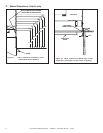
NOTE 2: Termination in an alcove space (spaces open only on one side
and with an overhang) are permitted with the dimensions specified for
vinyl or non-vinyl siding and soffits. 1. There must be 3 feet minimum
between terminations or between the appliance and termination. 2. All
mechanical air intakes within 10 feet of a termination must be a minimum of
3 feet below the appliance hood. 3. All gravity air intakes within 3 feet of
the appliance hood must be a minimum of 1 foot below the termination.
* 36” minimum for vinyl windows or vinyl siding.
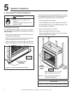
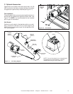
This appliance is approved for installation onto screened porches
with the following guidelines:
Fire Risk. Explosion Risk.
Maintain vent termination minimum clearances as specified.
WARNING
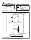
Figure 4.1 Minimum Clearances for Appliance Opening
NOTE: There may be some odor and small amounts of soot
associated with venting the Twilight-II onto a screened porch.
Ensuring good cross draft ventilation and routine maintenance of
the appliance will maximize comfort and cleanliness.
Minimum porch area: 96 square feet
Minimum ceiling height: 92 inches
Minimum two walls must be screened
Minimum top of screen height, side walls: 6 ft. 8 in.
Minimum screen area: 64 square feet
A. Appliance Opening
Minimum Clearances
M
N
P
R
Q
FP