


Heat & Glo LifeStyle Collection • Twilight-II • 2087-900 Rev. G • 12/05 15
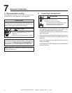
Wall Switch
Position the wall switch in the desired position on a wall.
Run a maximum of 25 feet (7.8 m) or less length of 18
A.W.G. minimum wire and connect it to the appliance ON/
OFF switch pigtails.
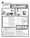
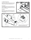
Fan Installation
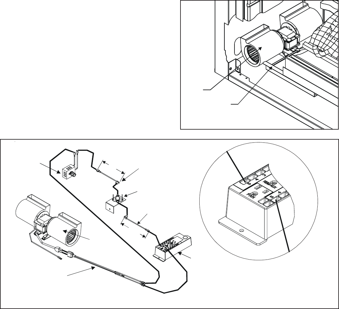
To provide best airflow, we recommend positioning fan on
the left side (as viewed from appliance interior side - see
Figure 7.2). NOTE: It is recommended fan be installed
prior to gas line installation.
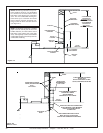
Figure 7.1 Fan Wiring Diagram
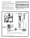
C. Optional Accessories
Optional fan and remote control kits require that 110-120
VAC be wired to the factory installed junction box before
the appliance is permanently installed (see Figure 7.1).
NOTE: If any of the original wire as supplied with
the appliance must be replaced, it must be
replaced with the type 105
o
C rated wire.
Figure 7.2 Fan location
FAN
DRIP
TRAY
SEE DETAIL A
WIRE LEAD
2 FEMALE ENDS
PLUG AND WIRE
ASSEMBLY
JUNCTION BOX
6 FT.
APPROX.
TEMPERATURE
SENSOR SWITCH
FAN SPEED
CONTROL
(RHEOSTAT)
DETAIL A
WIRE LEAD
1 MALE END
1 FEMALE END
6 FT.
APPROX.
FAN KIT
#GFK-160T
APPLIANCE
INTERIOR
SIDE