


8
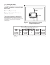
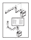
MODEL FLUE TERMINATION APPROVALS
ST-38HV-AU DVK-01DA, DVK-01TR
DVK-03DA DVK-TVCD
TABLE 1
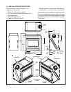
1.3 FLUE SYSTEM APPROVALS AND
INSTALLATIONS
This model is approved to use D-Series flue pipe
components. A DVK-01DA, DVK-03DA or DVK-01TR
Termination Cap must be used to terminate vent sys-
tems in a horizontal position. DVK-TVCD vertical Ter-
mination Caps must be used to terminate vent systems
in a vertical position.
Figures 6 through 10 show the flue systems approved
for use with these models. Approved flue system com-
ponents are labeled for identification. NO OTHER FLUE
SYSTEMS OR COMPONENTS MAY BE USED. De-
tailed installation instructions are included with each
flue termination kit and should be used in conjunction
with this manual.
WARNING: THIS GAS APPLIANCE AND FLUE AS-
SEMBLY MUST BE FLUED DIRECTLY TO THE OUT-
SIDE AND MUST NEVER BE ATTACHED TO A CHIM-
NEY SERVING A SEPARATE SOLID FUEL BURNING
APPLIANCE. EACH GAS APPLIANCE MUST USE A
SEPARATE FLUE SYSTEM-COMMON FLUE SYSTEMS
ARE PROHIBITED.
CAUTION: UNDER NO CONDITION SHOULD COM-
BUSTIBLE MATERIAL BE CLOSER THAN 3 INCHES
(2 1/2 INCHES AT WALL FIRESTOPS) FROM THE TOP
OF THE 8 5/8-INCH PIPE OR 1-INCH TO THE SIDES
AND THE BOTTOM FOR HORIZONTAL SECTIONS OF
THIS FLUE SYSTEM. VERTICAL SECTIONS OF THIS
SYSTEM REQUIRE A MINIMUM OF 1-INCH CLEAR-
ANCE TO COMBUSTIBLE MATERIALS ALL AROUND
THE 8 5/8 - INCH PIPE.
For alternative installations, other than depicted, con-
tact your dealer for further information.
Refer to Figure 4 for required clearances to flue termi-
nals.
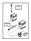
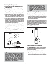
STRAIGHT OUT HORIZONTAL FLUE
SYSTEM
Figure 6 shows straight out horizontal flue systems and
straight up vertical flue systems approved for use on
this model.
ELBOWS
The flue systems installed on this gas heater may also
include one (1), two (2), or three (3) 90 - degree elbow
assemblies, in addition to the 45 - degree elbow re-
quired at the unit.
Figures 7 through 10 and their corresponding tables show
examples of vent configurations using elbows. The rela-
tionships of vertical rise to horizontal run in vent con-
figurations using elbows MUST be strictly adhered to.
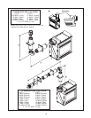
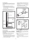
ONE (1) 90-DEGREE ELBOW
Figure 7 shows an installation using one (1) 90-degree
elbow. Dimension V is listed as MINIMUM vertical di-
mensions and dimension H is listed as corresponding
MAXIMUM horizontal dimensions.
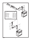
TWO (2) 90-DEGREE ELBOWS
Figure 8 shows examples of possible installations us-
ing two (2) 90-degree elbows. Dimension V is listed as
MINIMUM vertical dimensions, dimension H is listed
as MAXIMUM beginning horizontal dimensions, and
dimension H+H
1
is listed as corresponding TOTAL
MAXIMUM horizontal dimensions.
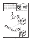
THREE (3) 90-DEGREE ELBOWS
Figures 9 and 10 show examples of possible installa-
tions using three (3) 90-degree elbows. Dimensions V
are listed MINIMUM first vertical dimensions and di-
mensions H are listed as beginning MAXIMUM hori-
zontal dimensions. Dimensions H+H
1
and
H+H
1
+H
2
are
listed as TOTAL MAXIMUM horizontal dimensions.
Dimensions V+V
1
are listed as TOTAL MAXIMUM ver-
tical dimensions.
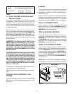
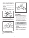
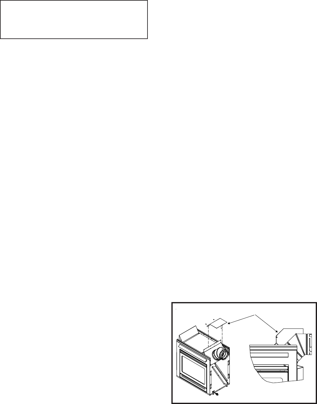
NOTE: When the 45
0
elbow is attached horizontally,
the supplied heat shield must be installed (see Figure 5).
Figure 5
HEAT SHIELD