


27
3.1 REMOVAL OF COVERS FOR
SERVICING
A. Control Compartment Grille
• Rotate the bottom grille down to access the gas
controls.
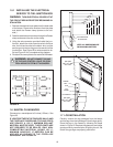
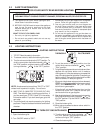
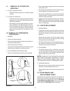
B. Trim door and Glass Door
• Lift the front trim door up and out away from the
appliance side surrounds. Replace the door when
servicing is complete.
• Note carefully how the glass assembly is held in
place. Release the two spring latches at the bot-
tom of the glass door. Next, remove wing nuts
from the top of the glass door. Carefully lift the
glass up and out away from the appliance. See
Figure 31.
3.2 REMOVAL OF COMPONENTS
FOR SERVICE
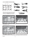
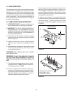
1. BURNER
• Remove the logs and grate.
• Remove the top refractory brackets and carefully re-
move the side refractories.
• Remove the bottom refractory.
• Unscrew the brackets at both ends of the burner and
slide the burner away from the burner orifice.
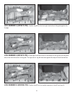
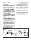
2. PILOT ASSEMBLY/IGNITION SYSTEM
• Remove the log set/log grate/refractory assembly.
• Disconnect the gas supply tube from the underside
of the pilot burner.
• Disconnect the electrode wire from the piezo ignitor
(found adjacent to the gas control valve).
• Disconnect the attachment nut from the underside
of the thermopile. The thermopile can then be sepa-
rated from the pilot bracket.
• Unscrew the pilot assembly bracket and remove.
NOTE: When removing the pilot assembly, carefully
pull the electrode wire up through the grommeted
hole in the base pan.
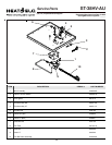
3.3 PARTS REPLACEMENT
1. FAN/SWITCHES
• Unplug the fan wires from the junction box wires by
pulling the male and female connectors apart and
slide the fan out the front of the lower controls com-
partment.
• Disconnect the wires from the fan speed control
switch, pull off the knob, and remove the nut holding
the speed control to the bracket.
• Disconnect the wires from the fan temperature sen-
sor switch and remove the nut holding the switch
bracket onto the side of the firebox.
2. GLASS PANEL
• To replace the glass door, locate the 4 top holes
over the bolts above the opening, push glass against
the unit and attach 2 lower tension springs. Hand
tighten wing nuts into top 4 bolts.
NOTE: WING NUTS THAT SECURE THE GLASS
ONLY NEED TO BE HAND TIGHTENED TO GIVE A
SNUG FIT FOR PROPER GASKET SEAL. OVER-
TIGHTENING MAY RESULT IN DAMAGED GLASS.
3. OVERHEAT SWITCH
• Remove the two screws holding the switch to the
top left front of the sheetmetal surround.
• Disconnect the wire from the switch and remove the
switch.
3.4 ADJUSTMENTS AND
REPLACEMENT PARTS
Adjustments and replacement parts for this appliance
should only be done by a qualified service person. A
wiring diagram for the appliance is shown in SECTION
2.0 OPERATING INSTRUCTIONS. A replacement part
table is shown in SECTION 4.0 of this manual.
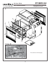
FIGURE 31
TENSION SPRING
LATCH
GLASS ASSEMBLY
WING NUT
LATCH
BRACKET