


17
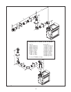
Figure 20
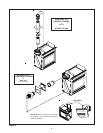
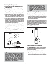
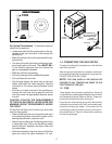
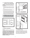
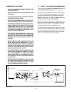
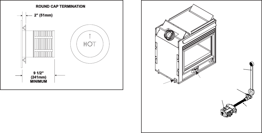
1.4 CONNECTING THE GAS SUPPLY
The gas is introduced to the appliance on the left hand
side. See Figure 20.
After the gas pipe installation is complete, check care-
fully all gas connections for leaks with a soap solution.
DO NOT USE AN OPEN FLAME.
NOTE: THE GAS SUPPLY LINE SHOULD BE
PURGED OF ANY TRAPPED AIR PRIOR TO THE
FIRST FIRING OF THE UNIT.
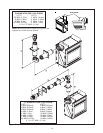
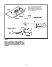
1.5 FAN
These heaters have a factory installed Fan, Electrical
Junction Boxes, variable speed Rheostat Control Switch
and Temperature Sensor Switch for the fan. These com-
ponents are located behind the lower grille.
Use of the fan requires that the Junction Box (factory
installed) be connected to 240 VAC service before per-
manently enclosing the heater. The access hole for
connecting the service wires is found on the lower ex-
terior side of the unit. Figure 21 shows the fan, switches,
and fan wiring diagram.
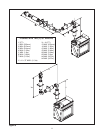
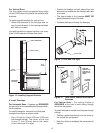
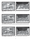
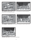
Figure 19 Round Termination Caps
For Vertical Terminations - To locate the flue and
install the flue sections:
• Locate and mark the flue center point on the un-
derside of the roof, and drive a nail through the
center point.
• Make the outline of the roof hole around the cen-
ter point nail.
• The size of the roof hole framing dimensions de-
pend on the pitch of the roof. There MUST BE a
1-inch (25mm) clearance from the vertical flue
pipe to combustible materials.
• Mark the roof hole accordingly.
• Cover the opening of the installed flue pipes.
• Cut and frame the roof hole.
• Use framing lumber the same size as the roof
rafters and install the frame securely. Flashing
anchored to the frame must withstand heavy
winds.
• Continue to install concentric flue sections up
through the roof hole and up past the roof line
until you reach the appropriate distance above
the roof.
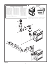
CAUTION: FOLLOW THE REQUIREMENTS
OF THE AGA GAS INSTALLATION CODE FOR
MINIMUM HEIGHT REQUIREMENTS ABOVE
THE ROOF.
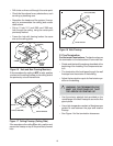
To seal the roof hole, and to divert rain and snow
from the flue system:
• Attach a flashing to the roof using nails, and use a
non-hardening mastic around the edges of the
flashing base where it meets the roof.
• Attach a storm collar over the flashing joint to form
a water-tight seal. Place non-hardening mastic
around the joint, between the storm collar and
the vertical pipe.
• Slide the termination cap over the end of the flue
pipe and rotate the pipe clockwise 1/4 turn.
GAS LINE
ACCESS
CONTROL
VALVE
USE A WRENCH ON
SHUT-OFF VALVE WHEN
TIGHTENING GAS LINE
GAS VALVE
FLEX
CONNECTOR
MANUAL
SHUT-OFF VALVE