


6
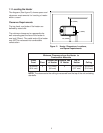
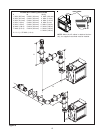
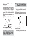
Minimum Clearances from the Flue Pipe to
Combustible Materials
For Vertical
For Horizontal Sections Sections At Wall Firestops
Top Bottom Sides Top Bottom Sides
3 inches 1 inch 1 inch 1 inch 2-1/2 inches 1/2 inch 1 inch
(75mm) (25mm) (25mm) (25mm) (64mm) (13mm) (25mm)
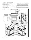
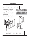
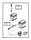
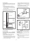
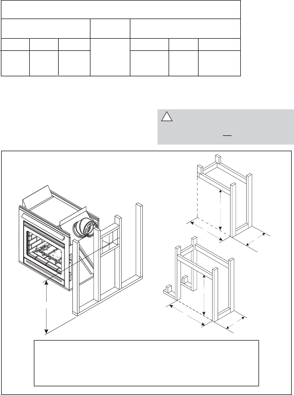
Figure 3. Framing Dimensions
For minimum clearances, see the direct vent
termination clearance diagrams on page 7.
1.2 Framing the Heater
Framing can be built before or after the heater is
set in place. Framing should be positioned to
accommodate wall coverings and heater facing
material. The diagram below shows framing
reference dimensions.
!
WARNING: FRAMING DIMENSIONS AS-
SUME USE OF 1/2 INCH THICK WALL
COVERING MATERIALS ON EXTERIOR OF
FRAMING ONLY AND NO SHEETROCK ON IN-
TERIOR OF FRAMING.
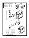
A
C
B
A
C
B
CAUTION: MEASURE HEATER DIMENSIONS
AND VERIFY FRAMING METHODS AND WALL
COVERING DETAILS, BEFORE FRAMING CON-
STRUCTION BEGINS.
D
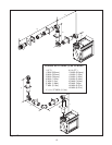
Model: ST-38HV-AU A B C D
45
0
Elbow (Horizontal) Flue 41" 43 1/4" 21 9/16" 37 1/8"
(1041mm) (1099mm) (548mm) (943mm)
45
0
Elbow (Vertical) Flue 42 3/4" 40 3/4" 21 9/16"
-
(1086mm) (1035mm) (548mm)
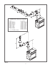
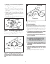
Shows center of 12" x 12” (305mm x 305mm) flue framing
holes. The center of the hole is 25mm above the center
of the horizontal flue pipe. Framing should be constructed
of 2" x 4" (51mm x 102mm) lumber or heavier.