


19
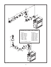
FIGURE 24
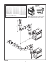
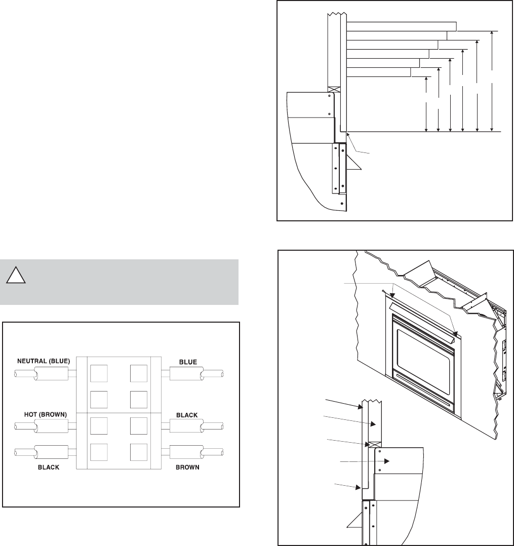
FIGURE 23
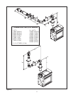
FIGURE 22
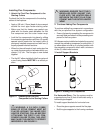
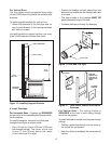
1.5.1 INSTALLING THE ELECTRICAL
SERVICE TO THE JUNCTION BOX
WARNING:
TURN ELECTRICAL POWER OFF AT
THE CIRCUIT BREAKER BEFORE BEGINNING IN-
STALLATION.
1. Remove the electrical cover plate from the lower side
of the heater. Remove the knockout from the plate
and attach the Romex clamp (screws to the out-
side.)
2. Feed the electrical services wires through the Romex
clamp and secure the wire to the clamp.
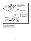
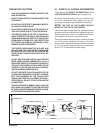
3. Using the wire connector provided inside the junc-
tion box, attach the neutral service wire to the blue
wire, the hot service wire to the black wire, and the
service ground wire to the ground screw stud of the
junction box. See Figure 22 for wire connection de-
tail and Figure 21 for a complete wiring diagram.
4. Re-attach the cover plate to the outside of the heater.
WARNING: DO NOT CONNECT 220 VAC
TO THE GAS CONTROL VALVE OR CON-
TROL WIRING SYSTEM OF THIS MODEL.
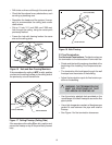
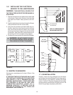
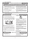
1.6 MANTEL CLEARANCES
Clearance to a mantelpiece is 6-inches (152mm). See
Figure 23.
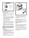
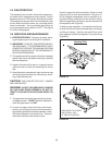
IF JOINTS BETWEEN THE FINISHED WALLS AND
THE FIREPLACE SURROUND (TOP AND SIDES)
ARE SEALED, A 150°
C. MINIMUM SEALANT
MATERIAL MUST BE USED. THESE JOINTS ARE
NOT REQUIRED TO BE SEALED. ONLY NON-
COMBUSTIBLE MATERIAL (USING 150° C.
MINIMUM ADHESIVE, IF NEEDED) CAN BE
APPLIED AS FACING TO THE FIREPLACE
SURROUND. SEE FIGURE 24.
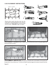
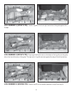
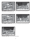
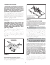
1.7 LOG INSTALLATION
Carefully remove the log packages from the heater
and the tags from their packages. Handle logs gently.
Place the logs in the heater by following the steps
shown in Figure 25. Replace the glass door and dress
guard previously removed prior to lighting the unit. Be
certain the gas logs are properly positioned.
NOTE: ALL DIMENSIONS ARE
SHOWN IN MILLIMETERS
.
TOP FRONT EDGE
OFFIREPLACE
152
178
229
254
279
152
178
203
229
254
279
203
HIGH TEMP
(300 F. 150C.MIN.)
SEAL JOINT
oo
STUD
TOP STANDOFF
FINISHED
WALL
2 X4
HEADER
HIGH TEMP
(300 F. 150C.MIN.)
SEAL JOINT
oo
!