


Heat & Glo • PALOMA-BZ-MOD, PALOMA-GR-MOD, PALOMA-GY-MOD • 2189-900 Rev. i • 5/1214
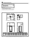
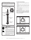
8 in.
(203 mm)
7 in.
(178 mm)
7 in.
(178 mm)
6 in.
(152 mm)
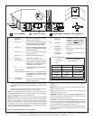
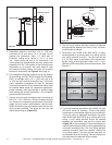
5. Installation requires a minimum of 6 in. (152 mm)
horizontal run of vent with a 1/4 in. (6 mm) rise run
towards the termination. Each 1 ft. (305 mm) of
horizontal venting must include a 1/4 in. (6 mm)
rise. Never allow the vent to run downward. This
could cause high temperatures and may present the
possibility of a fire. The location of the horizontal vent
termination on an exterior wall must meet all local
and national building codes, and must not be easily
blocked or obstructed, see Figure 4.4 on page 10.
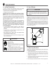
6. For installations requiring a vertical rise on the exterior
of the building, the HHT RHVK snorkel kit (Part #844-
8921) is available with a 14 in. (356 mm) and a 36
in. (914 mm) tall snorkel termination cap. Follow the
same installation procedures as used for standard
horizontal terminations. If the snorkel termination must
be installed below grade (i.e. basement application),
proper drainage must be provided to prevent water
from entering the snorkel termination. Do not backfill
around snorkel termination.
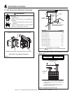
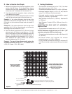
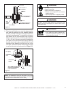
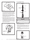
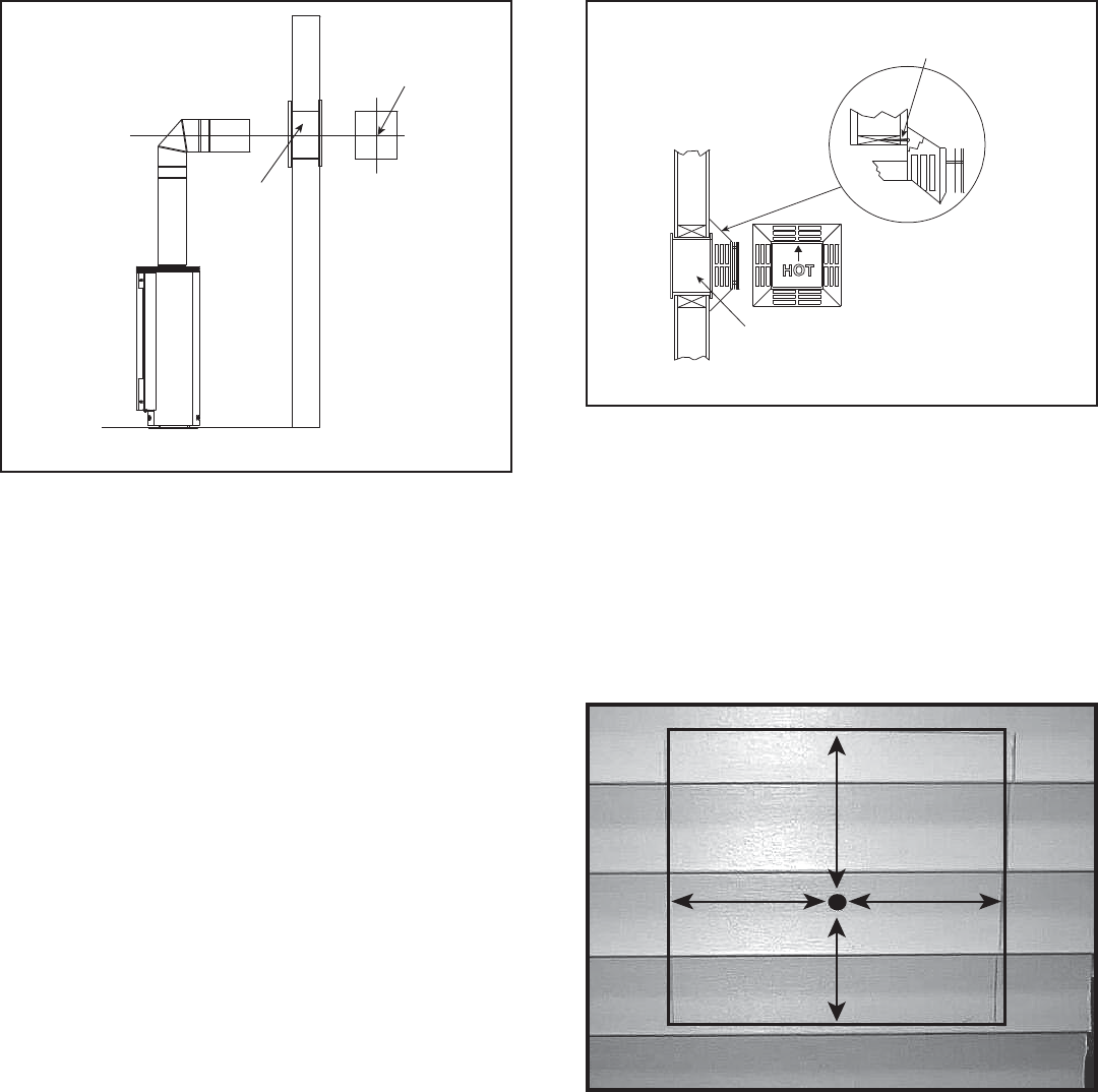
7. Position the horizontal termination cap in the center of
the 10 in. x 10 in. (254 mm x 254 mm) square hole and
run a bead of non-hardening mastic around its outside
edges, so as to make a seal between it and the wall,
attach termination cap to the exterior wall with the four
wood screws provided. The arrow on the vent cap
should be pointing up (Figure 5.6).
Figure 5.6
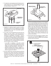
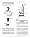
Figure 5.7
10. If you are installing termination cap HHW2, the pipe
will be off center on flashing). Ensure that proper
clearances to combustible materials are maintained.
If you are using an approved termination cap other
than HHW2 (part #841-0670) on a building with vinyl
siding, a vinyl siding standoff should be installed
between the termination cap and the exterior wall
(Figure 5.8, on the next page). Follow manufacturer’s
instructions for attaching the vinyl siding standoff to the
horizontal termination cap. The vinyl siding standoff
prevents excessive heat from possibly melting the
vinyl siding material. The vent terminal cap shall not
be recessed into a wall or siding. Remove siding from
the area where the standoff will be located.
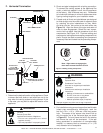
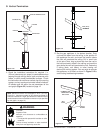
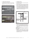
Figure 5.5
CENTER LINE
CENTER OF HOLE
WALL
THIMBLE
CENTER LINE
8. The four wood screws provided should be replaced
with appropriate fasteners for stucco, brick, concrete,
or other types of sidings.
9. Termination cap HHW2 (Part #841-0670) is highly
recommended on a building with vinyl siding, as the
vinyl siding standoff is built in. The pilot hole will be
2 in. (51 mm) closer to the bottom of the square than
the top. Using a framing square, draw a 14 in. x 14 in.
(356 mm x 356 mm) square around the pilot hole. See
Figure 5.7.
HOT
WOOD
SCREW
WALL THIMBLE
PART HHW2 #841-0670
(PREFERRED)