


13
Heat & Glo • PALOMA-BZ-MOD, PALOMA-GR-MOD, PALOMA-GY-MOD • 2189-900 Rev. i • 5/12
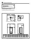
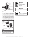
Figure 5.3
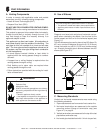
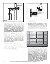
Figure 5.4 Adding Venting Components
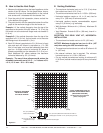
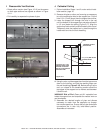
4. For installations using a round support box/wall thimble
(check pipe manufacturer's instructions), mark the
wall for a 10 in. x 10 in. (254 mm x 254 mm) square
hole. The center of the square hole should line up
with the center line of the horizontal pipe, as shown
in Figure 5.5. Cut and frame the hole in the exterior
wall where the vent will be terminated. If the wall
being penetrated is constructed of noncombustible
material, i.e. masonry block or concrete, a 7 in. (178
mm) diameter hole is acceptable.
TRIM RING
STANDARD
WALL THIMBLE
CENTER LINE
MINIMUM OF 6 IN. (152 MM) OF
PIPE THROUGH THE WALL
INTERIOR WALL
- 2 IN. (51 MM)
CLEARANCE FROM
REAR OF STOVE
SLIM LINE
WALL THIMBLE
OR
CHOOSE BETWEEN
TERMINATION CAP
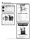
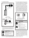
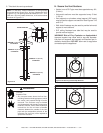
F. Horizontal Termination
90º ELBOW
PIPE LENGTH
WALL THIMBLE COVER
WALL THIMBLE
TERMINATION CAP
PIPE LENGTH
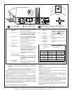
Fire Risk
Exhaust Fumes Risk
Impaired Performance of Appliance
• Ensure vent components are locked
together correctly.
• Pipe may separate if not properly joined.
WARNING
Fire Risk.
Explosion Risk.
Combustion Fume Risk.
Use vent run supports per installation
instructions.
Connect vent sections per installation
instructions.
• Maintain all clearances to combustibles.
• Do NOT allow vent to sag below
connection point to appliance.
• Maintain specifi ed slope (if required).
Improper support may allow vent to sag or separate.
WARNING
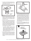
1. Determine the desired location of the appliance. Check
to ensure that wall studs or roof rafters are not in the
way when the venting system is being planned. If this
is the case, you may want to adjust the location of the
appliance.
2. Direct vent pipe is designed with a locking connection.
To connect the venting system to the appliance flue
outlet, a twist-lock adapter is built into the appliance
at the factory. Wall thickness may vary. Remember
to include wall thickness in minimum clearances when
figuring venting lengths for your installation needs.
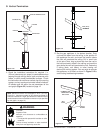
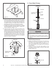
3. Female ends of direct vent pipe/elbows are designed
to slide straight onto the male ends of adjacent pipes
by orienting the pipe indentations so they match
and slide into the entry slots on the male ends, see
Figure 5.4. Align the seam of the pipe and seam of
collar to allow engagement. Rotate the vent compo-
nent to lock into place. Use this procedure for all vent
components. See Figure 10.5. Continue adding vent
components, locking each succeeding component into
place. Ensure that each succeeding vent component
is securely fi tted and locked into the preceding compo-
nent.
Note: Align seams to engage pipe,
then rotate counterclockwise to lock