


8
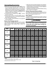
Overcurrent Protection
Overcurrent protection must be provided at the branch
circuit distribution panel and sized as shown on the unit
rating label and according to applicable local codes.
Generally, the best fuse or breaker for any heat pump
is the smallest size that will permit the equipment to run
under normal usage and provide maximum equipment
protection. Properly sized fuses and breakers also prevent
nuisance trips during unit startup. If a fuse blows or a
breaker trips, always determine the reason. Do not
arbitrarily install a larger fuse or breaker and do not,
in any case, exceed the maximum size listed on the
data label of the unit.
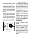
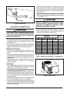
Grounding
WARNING:
The unit cabinet must have an uninterrupted or
unbroken electrical ground to minimize personal
injury if an electrical fault should occur. Do not
use gas piping as an electrical ground!
This unit must be electrically grounded in accordance
with local codes or, in the absence of local codes, with
the National Electrical Code (ANSI/NFPA 70) or the CSA
C22.1 Electrical Code. Use the grounding lug provided in
the control box for grounding the unit.
Thermostat Connections
• Theheat-coolthermostatisequippedwithasystem
HEAT-COOL switch, which provides a positive means
of preventing simultaneous operation of the heating and
cooling units. The thermostat is also equipped with an
ON-AUTO fan switch which allows the home owner to
operate the indoor blower when air circulation is desired.
• Connectthelowvoltagewirestotherespectiveterminals
on the thermostat base (Figure 11, page 22). See
thermostat instruction sheet for more detailed wiring
information.
• Thethermostatshouldbemountedabout5feetabovethe
floor on an inside wall. DO NOT install the thermostat on
an outside wall or any other location where its operation
may be adversely affected by radiant heat from fireplaces,
sunlight, or lighting fixtures, and convective heat from
warm air registers or electrical appliances. Refer to the
thermostat manufacturer’s instruction sheet for detailed
mounting information.
Defrost Cycle Control
The defrost cycle is initiated via a signal from the defrost
sensor on the outdoor coil to the defrost control board inside
the control panel. This indicates the coil temperature is low
enough to start accumulating frost. The board has interval
settings of 30, 60, and 90 minutes. These time intervals
represent the time elapsed before defrosting cycle starts
and they are dependent on the climate conditions of the
installation. A 30 minute setting would be recommended
in a moist climate such as Seattle Washington. A 90
minute setting would be adequate in a dry climate such
as southern Arizona. The factory time interval setting is
30 minutes.
Defrost Control Board
Operational Information
• Terminals R - C must have 24V present between
them for the time delay and defrost sequences to be
operational.
• Defrost Thermostat (DFT) By-Pass - Jumping the
T2 & DFT test pins will communicate to the board that
the defrost thermostat is closed (if the compressor is
running). The defrost T-stat tells the board whether a
defrost cycle needs to be started or terminated.
NOTE: The defrost T-stat is closed at 30° F or below
and is open at 68° F or above, but its state is unknown
if the temperature is between 30° F and 68° F.
• With the DFT closed, the unit will run for 30/60/90
minutes in heat mode and then defrost the outdoor
coil. The defrost will turn off the outdoor fan, energize
the reversing valve, and turn on the compressor raising
the coil temperature to 68° F. This will open the DFT
and terminate the defrost. If the DFT does not open,
the defrost will end after 10 minutes.
• Defrost Board Speed Up - Jumping the TEST terminal
to the C (common) terminal (while the compressor is in
heat mode) will over-ride the defrost board and initiate a
faster defrost test in 5, 10 or 15 seconds as determined
by the 30, 60 or 90 minute defrost pin settings (factory
setting is 30 minutes).
– The compressor off delay is also bypassed when the
unit goes into defrost test. If unit is kept in defrost
test, the delay will be bypassed when the test is
terminated by the processor.
NOTE: If the jumper is removed before the test is over,
the processor will perform the remainder of a normal
defrost as noted above.
• The delay/no-delay pin affects compressor operation
during defrosts. The default setting is delay. To switch
from delay to no-delay, remove the pin from the delay
pin location and move it to the no-delay pin location.
- Scroll compressors that have noise issues while
going into or coming out of defrost should use this
30 second delay to reduce the defrost noise.
Normal Mode
To test normal defrost operation when the temperature is
above 35° F, jumper R to DFT on the board and allow the
unit to run for 30 minutes. Defrost will continue until the
R to DFT jumper is removed or for 10 minutes. Remove
the jumper.
The 5 minute time delay feature can be shortened 1 time
to 1 second by jumping the Test to C terminal. Remove
the jumper and repeat as desired. NOTE: If jumper is left
on the Test to common pins permanently, the defrost
cycle will be inoperable.