


7
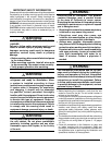
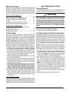
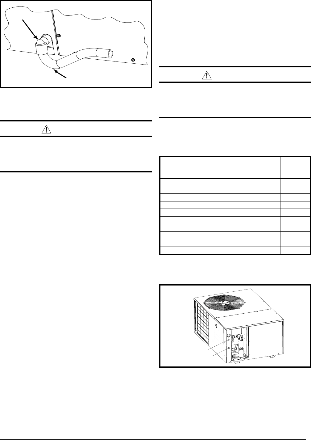
Figure 5. Drain Trap
Elbow
P-Trap
ELECTRICAL CONNECTIONS
WARNING:
To avoid electric shock, personal injury, or death,
turn off the electric power at the disconnect
or the main service panel before making any
electrical connections.
• Electrical connections must be in compliance with
all applicable local codes and ordinances, and with
the current revision of the National Electric Code
(ANSI/NFPA 70).
• ForCanadianinstallationstheelectricalconnections
and grounding shall comply with the current Canadian
Electrical Code (CSA C22.1 and/or local codes).
Pre-Electrical Checklist
√ Verify that the voltage, frequency, and phase of the
supply source match the specifications on the unit rating
plate.
√ Verify that the service provided by the utility is sufficient
to handle the additional load imposed by this equipment.
Refer to the unit wiring label for proper high and low
voltage wiring.
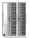
√ Verify factory wiring is in accordance with the unit wiring
diagram (Figures 8 - 10, pages 19 - 21). Inspect for
loose connections.
LineVoltage
• Itisrecommendedthatthelinevoltagetotheunitbe
supplied from a dedicated branch circuit containing the
correct fuse or circuit breaker for the unit.
• An electrical disconnect must be located within sight
of and readily accessible to the unit. This switch shall
be capable of electrically de-energizing the outdoor unit.
See unit data label for proper incoming field wiring. Any
other wiring methods must be acceptable to authority
having jurisdiction.
• Providepowersupplyfortheunitinaccordancewith
the unit wiring diagram, and the unit rating plate.
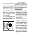
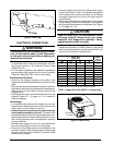
• Connecttheline-voltageleadstotheterminalsonthe
contactor inside the control compartment. Extend leads
through power wiring hole (Figure 6). Connect L1 & L2
directly to the contactor.
• Useonlycopperwireforthelinevoltagepowersupply
to this unit as listed in Table 1. Use proper code agency
listed conduit and a conduit connector for connecting
the supply wires to the unit. Use of rain tight conduit is
recommended.
• Seetheunitwiringlabelforproperhighandlowvoltage
wiring. Make all electrical connections in accordance
with all applicable codes and ordinances. See Figures
8 - 10 (pages 19 - 21).
CAUTION:
Label all wires prior to disconnection when
servicing controls. Wiring errors can cause
improper and dangerous operation. Verify
proper operation after servicing.
• Unitsareshippedfromthefactorywiredfor240volt
transformer operation. For 208V operation, remove the
lead from the transformer terminal marked 240V and
connect it to the terminal marked 208V.
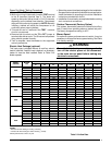
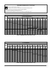
Supply Wire
Length (Feet)
Supply
Circuit
Ampacity
200 150 100 50
6 8 10 14 15
4 6 8 12 20
4 6 8 10 25
4 4 6 10 30
3 4 6 8 35
3 4 6 8 40
2 3 4 6 45
2 3 4 6 50
2 3 4 6 55
1 2 3 4 60
Wire Size based on N.E.C. for 60° type copper conductors.
Table 1. Copper Wire Size AWG (1% voltage drop)
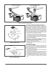
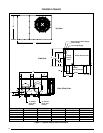
Figure 6. Power Entry
Low Voltage
High Voltage