


6
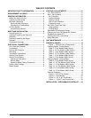
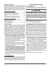
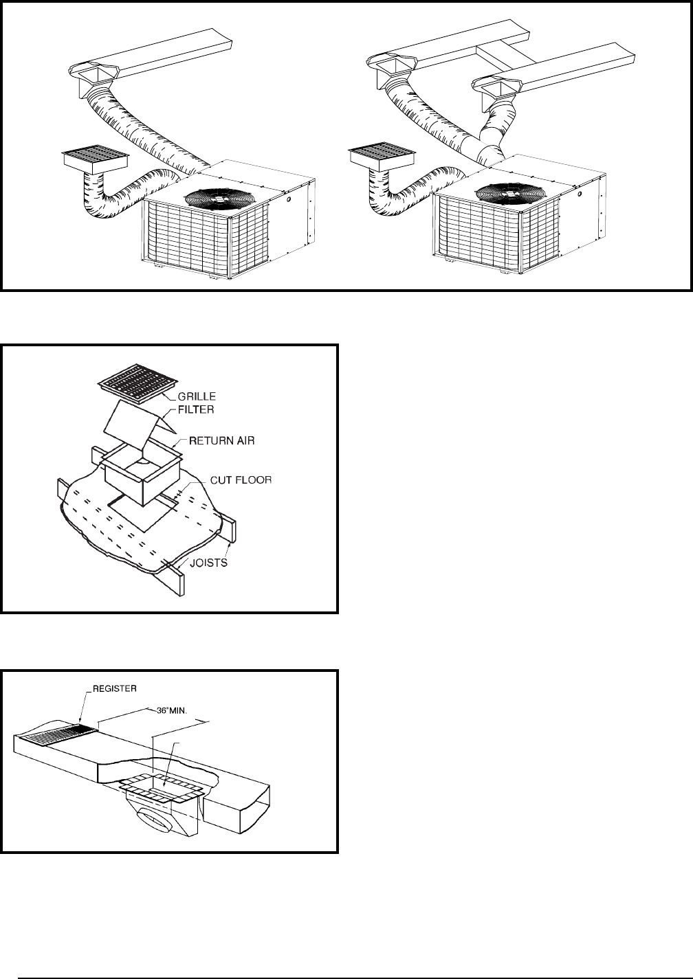
Figure 2. Typical Duct Applications
MULTIPLE DUCT APPLICATIONSINGLE DUCT APPLICATION
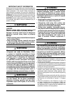
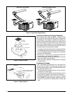
Figure 3. Return Air Box
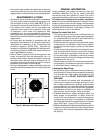
Figure 4. Supply Damper
AUTOMATIC DAMPER IS CLOSED
WHEN HEAT PUMP IS OFF
Locating & Installing the Supply Damper(s)
When locating the supply damper(s), carefully check
floor joists and frame members that could interfere with
the installation of the damper or flexible duct. Ideally, the
damper (Figure 4) should be located in the bottom of the
main duct, forward of center of the home, at least three
feet from the nearest register. The round supply opening
in the slanted side of the damper should face the side of
the home where the heat pump is located.
1. Locate the center of the heat duct by cutting a small hole
in the fiberboard below the duct at the desired location.
2. Cut a hole approximately 3/4” larger than the damper
opening in the fiberboard.
3. Cut a 9-1/8” x 13-1/8” hole in the duct and bend over
all tabs flat on the inside of the heat duct.
4. Insert the damper into the duct and bend over all tabs
flat on the inside of the heat duct.
5. Seal the opening between the fiberboard and damper
or flexible duct.
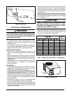
Condensate Drainage
A 3/4” condensate fitting extends out of the side of the
unit as shown in Figure 6. The drain trap, shipped in the
electrical compartment, must be installed to prevent water
from collecting inside the unit.
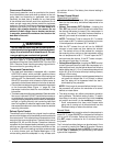
1. Thread the elbow provided with the unit into the drain
connection until hand tight.
2. Connect the condensate tubing onto the fitting, forming
a trap (Figure 5, page 7) near the drain connection.
3. Route the condensate tube from the trap to a suitable
drain. NOTE: For proper drainage, make sure the trap
is level to the ground and tubing outlet is below trap
level.