


45
Installation, Operation & Maintenance HTV/HTD/HTH SERIES Heat Controller, Inc.
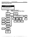
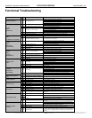
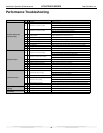
Functional Troubleshooting
Fault Htg Clg Possible Cause Solution
Main power problems
XXGreen Status LED Off
Check line voltage circuit breaker and disconnect.
Check for line voltage between L1 and L2 on the contactor.
Check for 24VAC between R and C on CXM/DXM'
Check primary/secondary voltage on transformer.
HP Fault
Code 2
High Pressure
X Reduced or no water fl ow in cooling
Check pump operation or valve operation/setting.
Check water fl ow adjust to proper fl ow rate.
X Water Temperature out of range in cooling Bring water temp within design parameters.
X Reduced or no air fl ow in heating
Check for dirty air fi lter and clean or replace.
Check fan motor operation and airfl ow restrictions.
Dirty Air Coil- construction dust etc.
Too high of external static. Check static vs blower table.
X Air temperature out of range in heating Bring return air temp within design parameters.
XXOvercharged with refrigerant Check superheat/subcooling vs typical operating condition table.
XXBad HP Switch Check switch continuity and operation. Replace.
LP/LOC Fault
Code 3
Low Pressure / Loss of Charge
XXInsuffi cient charge Check for refrigerant leaks
X Compressor pump down at start-up Check charge and start-up water fl ow.
LT1 Fault
Code 4
Water coil low
temperature limit
X Reduced or no water fl ow in heating
Check pump operation or water valve operation/setting.
Plugged strainer or fi lter. Clean or replace..
Check water fl ow adjust to proper fl ow rate.
X Inadequate antifreeze level Check antifreeze density with hydrometer.
X
Improper temperature limit setting (30°F vs
10°F [-1°C vs -2°C])
Clip JW3 jumper for antifreeze (10°F [-12°C]) use.
X Water Temperature out of range Bring water temp within design parameters.
XXBad thermistor Check temp and impedance correlation per chart
LT2 Fault
Code 5
Air coil low
temperature limit
X Reduced or no air fl ow in cooling
Check for dirty air fi lter and clean or replace.
Check fan motor operation and airfl ow restrictions.
Too high of external static. Check static vs blower table.
X Air Temperature out of range Too much cold vent air? Bring entering air temp within design parameters.
X
Improper temperature limit setting (30°F vs
10°F [-1°C vs -12°C])
Normal airside applications will require 30°F [-1°C] only.
XXBad thermistor Check temp and impedance correlation per chart.
Condensate Fault
Code 6
XXBlocked drain Check for blockage and clean drain.
XXImproper trap Check trap dimensions and location ahead of vent.
X Poor drainage
Check for piping slope away from unit.
Check slope of unit toward outlet.
Poor venting. Check vent location.
X Moisture on sensor Check for moisture shorting to air coil.
XXPlugged air fi lter Replace air fi lter.
xXRestricted Return Air Flow Find and eliminate restriction. Increase return duct and/or grille size.
Over/Under
Voltage Code 7
(Auto resetting)
XXUnder Voltage
Check power supply and 24VAC voltage before and during operation.
Check power supply wire size.
Check compressor starting. Need hard start kit?
Check 24VAC and unit transformer tap for correct power supply voltage.
XXOver Voltage
Check power supply voltage and 24VAC before and during operation.
Check 24VAC and unit transformer tap for correct power supply voltage.
Unit Performance Sentinel
Code 8
X Heating mode FP2>125°F [52°C] Check for poor air fl ow or overcharged unit.
X
Cooling Mode FP1>125°F [52°C] OR FP2<
40ºF [4ºC])
Check for poor water fl ow, or air fl ow.
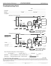
No Fault Code Shown
XXNo compressor operation See "Only Fan Operates".
XXCompressor overload Check and replace if necessary.
XXControl board Reset power and check operation.
Unit Short Cycles
XXDirty air fi lter Check and clean air fi lter.
XXUnit in "test mode" Reset power or wait 20 minutes for auto exit.
XXUnit selection Unit may be oversized for space. Check sizing for actual load of space.
XXCompressor overload Check and replace if necessary
Only Fan Runs
XXThermostat position Ensure thermostat set for heating or cooling operation.
XXUnit locked out Check for lockout codes. Reset power.
XXCompressor Overload Check compressor overload. Replace if necessary.
XXThermostat wiring
Check thermostat wiring at heat pump. Jumper Y and R for compressor operation
in test mode.
Only Compressor Runs
XXThermostat wiring Check G wiring at heat pump. Jumper G and R for fan operation
XX
Fan motor relay
Jumper G and R for fan operation. Check for Line voltage across BR contacts.
XX Check fan power enable relay operation (if present).
XXFan motor Check for line voltage at motor. Check capacitor.
XXThermostat wiring
Check thermostat wiring at heat pump. Jumper Y and R for compressor operation
in test mode
Unit Doesn’t Operate
in Cooling
X Reversing valve
Set for cooling demand and check 24VAC on RV coil and at CXM/DXM board.
If RV is stuck, run high pressure up by reducing water fl ow and while operating
engage and disengage RV coil voltage to push valve.
X Thermostat setup Check for ‘O’ RV setup not ‘B’.
X Thermostat wiring Check O wiring at heat pump. Jumper O and R for RV coil ‘click’.
X Thermostat wiring
Put thermostat in cooling mode. Check 24 VAC on O (check between C and
O); check for 24 VAC on W (check between W and C). There should be voltage
on O, but not on W. If voltage is present on W, thermostat may be bad or wired
incorrectly.