


43
Installation, Operation & Maintenance HTV/HTD/HTH SERIES Heat Controller, Inc.
General
If operational diffi culties are encountered, perform the preliminary
checks below before referring to the troubleshooting charts.
• Verify that the unit is receiving electrical supply power.
• Make sure the fuses in the fused disconnect switches
are intact.
After completing the preliminary checks described above,
inspect for other obvious problems such as leaking connections,
broken or disconnected wires, etc. If everything appears to
be in order, but the unit still fails to operate properly, refer to
the “CXM Troubleshooting Process Flowchart” or “Functional
Troubleshooting Chart.”
CXM Board
CXM board troubleshooting in general is best summarized as
simply verifying inputs and outputs. After inputs and outputs
have been verifi ed, board operation is confi rmed and the problem
must be elsewhere. Below are some general guidelines for
troubleshooting the CXM control.
Field Inputs
All inputs are 24VAC from the thermostat and can be verifi ed
using a volt meter between C and Y, G, O, W. 24VAC will be
present at the terminal (for example, between “Y” and “C”) if the
thermostat is sending an input to the CXM board.
Sensor Inputs
All sensor inputs are ‘paired wires’ connecting each component to
the board. Therefore, continuity on pressure switches, for example
can be checked at the board connector.
The thermistor resistance should be measured with the
connector removed so that only the impedance of the thermistor
is measured. If desired, this reading can be compared to the
thermistor resistance chart shown in the CXM AOM manual. An
ice bath can be used to check calibration of the thermistor.
Outputs
The compressor relay is 24VAC and can be verifi ed using a
voltmeter. The fan signal is passed through the board to the
external fan relay (units with PSC motors only). The alarm relay
can either be 24VAC as shipped or dry contacts for use with
DDC controls by clipping the JW1 jumper. Electric heat outputs
are 24VDC “ground sinking” and require a volt meter set for DC
to verify operation. The terminal marked “24VDC” is the 24VDC
supply to the electric heat board; terminal “EH1” is stage 1 electric
heat; terminal “EH2” is stage 2 electric heat. When electric heat
is energized (thermostat is sending a “W” input to the CXM
controller), there will be 24VDC between terminal “24VDC” and
“EH1” (stage 1 electric heat) and/or “EH2” (stage 2 electric heat).
A reading of 0VDC between “24VDC” and “EH1” or “EH2” will
indicate that the CXM board is NOT sending an output signal to
the electric heat board.
Test Mode
Test mode can be entered for 20 minutes by shorting the test
pins. The CXM board will automatically exit test mode after 20
minutes.
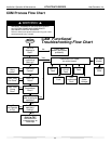
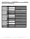
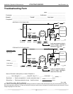
CXM Troubleshooting Process Flowchart/Functional
Troubleshooting Chart
The “CXM Functional Troubleshooting Process Flowchart”
is a quick overview of how to start diagnosing a suspected
problem, using the fault recognition features of the CXM board.
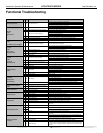
The “Functional Troubleshooting Chart” on the following page
is a more comprehensive method for identifying a number of
malfunctions that may occur, and is not limited to just the CXM
controls. Within the chart are fi ve columns:
• The “Fault” column describes the symptoms.
• Columns 2 and 3 identify in which mode the fault is likey to
occur, heating or cooling.
• The “Possible Cause column” identifi es the most likely sources
of the problem.
• The “Solution” column describes what should be done to
correct the problem.
WARNING! HAZARDOUS VOLTAGE! DISCONNECT
ALL ELECTRIC POWER INCLUDING REMOTE
DISCONNECTS BEFORE SERVICING.
Failure to disconnect power before servicing can cause
severe personal injury or death.
Troubleshooting
WARNING!