


11
Installation, Operation & Maintenance HTV/HTD/HTH SERIES Heat Controller, Inc.
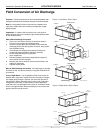
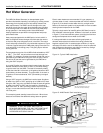
Water Connection Installation
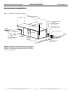
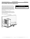
External Flow Controller Mounting
The Flow Controller can be mounted beside the unit as shown
in Figure 12. Review the Flow Controller installation manual for
more details.
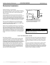
Gasket
Swivel Nut
Stainless steel
snap ring
Brass Adaptor
Hand Tighten
Only!
Do Not
Overtighten!
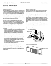
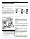
Figure 11: Water Connections
Pre-Installation
Prior to installation, locate and mark all existing underground
utilities, piping, etc. Install loops for new construction before
sidewalks, patios, driveways, and other construction has begun.
During construction, accurately mark all ground loop piping on
the plot plan as an aid in avoiding potential future damage to the
installation.
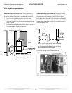
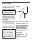
Piping Installation
The typical closed loop ground source system is shown in Figure
12. All earth loop piping materials should be limited to polyethylene
fusion only for in-ground sections of the loop. Galvanized or steel
fi ttings should not be used at any time due to their tendency to
corrode. All plastic to metal threaded fi ttings should be avoided due
to their potential to leak in earth coupled applications. A fl anged
fi tting should be substituted. P/T plugs should be used so that
fl ow can be measured using the pressure drop of the unit heat
exchanger.
Earth loop temperatures can range between 25 and 110°F [-4
to 43°C]. Flow rates between 2.25 and 3 gpm per ton [2.41 to
3.23 l/m per kW] of cooling capacity is recommended in these
applications.
Test individual horizontal loop circuits before backfi lling. Test
vertical U-bends and pond loop assemblies prior to installation.
Pressures of at least 100 psi [689 kPa] should be used when
testing. Do not exceed the pipe pressure rating. Test entire
system when all loops are assembled.
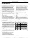
Flushing the Earth Loop
Once piping is completed between the unit, Flow Controller and
the ground loop (Figure 12), the loop is ready for fi nal purging
and charging. A fl ush cart with at least a 1.5 hp [1.1 kW] pump is
required to achieve enough fl uid velocity in the loop piping system
to purge air and dirt particles. An antifreeze solution is used in
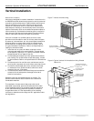
GROUND-LOOP HEAT PUMP APPLICATIONS
CAUTION!
High and
Low Voltage
Knockouts
Vibration Isolation Pad
To Thermostat
Figure 12: Typical Ground-Loop Application
CAUTION! The following instructions represent industry
accepted installation practices for closed loop earth coupled
heat pump systems. Instructions are provided to assist the
contractor in installing trouble free ground loops. These
instructions are recommendations only. State/provincial
and local codes MUST be followed and installation MUST
conform to ALL applicable codes. It is the responsibility of
the installing contractor to determine and comply with ALL
applicable codes and regulations.
Water Connections-Residential (Distributor) Models
Residential models utilize swivel piping fi ttings for water
connections that are rated for 450 psi (3101 kPa) operating
pressure. The connections have a rubber gasket seal similar to a
garden hose gasket, which when mated to the fl ush end of most
1” threaded male pipe fi ttings provides a leak-free seal without
the need for thread sealing tape or joint compound. Check for
burrs and ensure that the rubber seal is in the swivel connector
prior to attempting any connection (rubber seals are shipped
attached to the swivel connector). DO NOT OVER TIGHTEN or
leaks may occur.
The female locking ring is threaded onto the pipe threads which
holds the male pipe end against the rubber gasket, and seals the
joint. HAND TIGHTEN ONLY! DO NOT OVERTIGHTEN!